1-6-11 T6450EA
1. DC 105V (+B) Adjustment
Purpose: To obtain correct operation.
Symptom of Misadjustment: The picture is dark and
unit does not operate correctly.
Note: TP503(+B), TP504(GND), VR601 --- H.V./Power
Supply CBA
1. Connect the unit to AC Power Outlet. (exact
AC230V)
2. Input a color bar signal from RF (or Ext.) input and
leave it for at least 20 minutes.
3. Connect DC Volt Meter to TP503(+B) and
TP504(GND).
4. Adjust VR601 so that the voltage of TP503(+B)
becomes +105±0.5V DC.
2. H Adjustment
Purpose: To get correct horizontal position and size of
screen image.
Symptom of Misadjustment: Horizontal position and
size of screen image may not be properly displayed.
Note: R590 --- H.V./Power Supply CBA
1. Connect Frequency Counter to R590.
2. Set the unit to the Ext. mode and no input is neces-
sary. Enter the Service mode.
(See page 1-6-10.)
3. Operate the unit for at least 20 minutes.
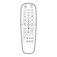
4. Press [2] button on the remote control unit and
select H-Adj Mode.
5. Press [P+/P-] buttons on the remote control unit so
that the display will change [0] to [7.]
At this moment, choose display [0] to [7] when the
Frequency counter display is closest to
15.625kHz±75Hz.
6. Turn the power off and on again.
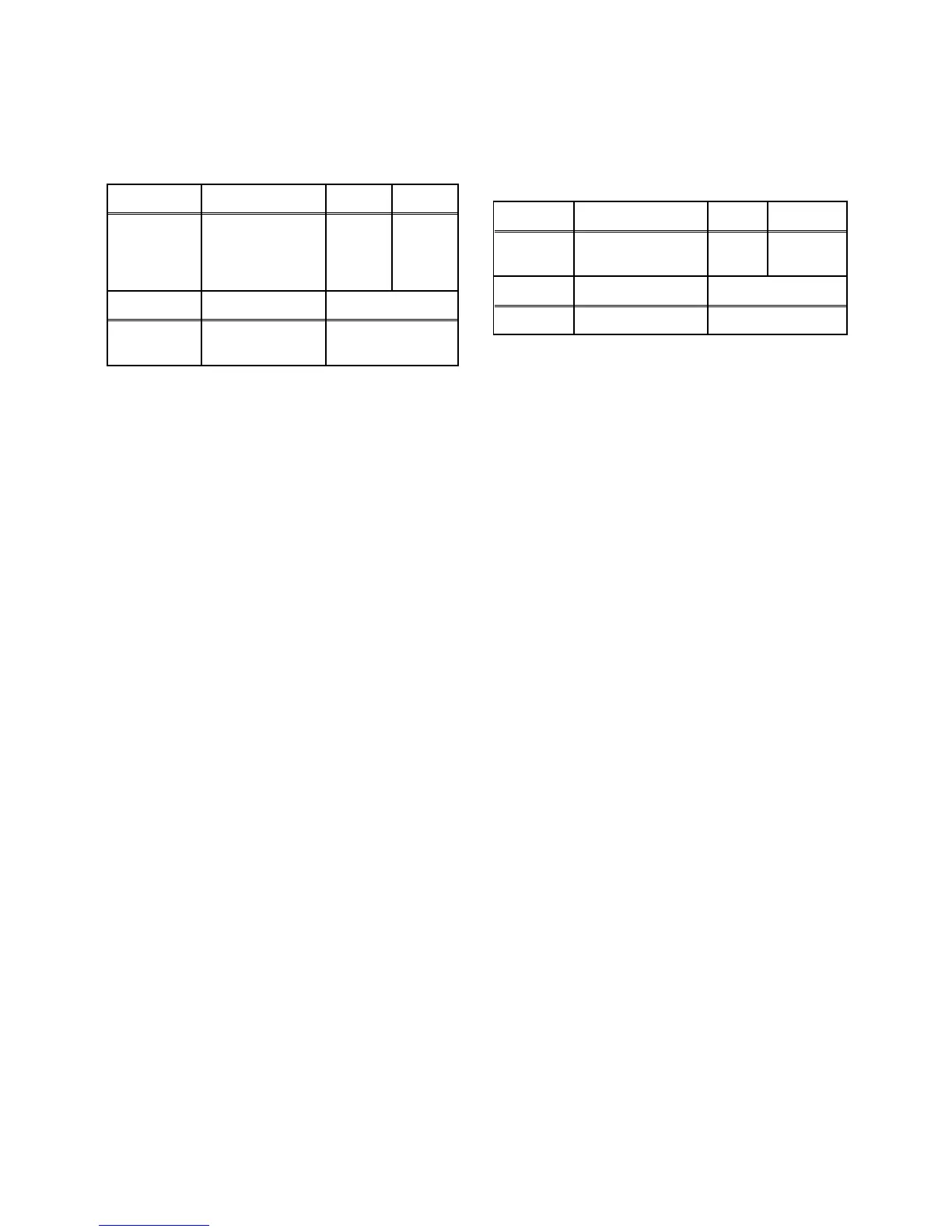
Test point Adj. Point Mode Input
TP503
(+B),
TP504
(GND)
VR601
RF
(or Ext.)
Color
Bar
Ta p e M . E Q . S p e c .
---
DC Voltmeter,
Plastic Tip Driver
+105±0.5V DC
Test point Adj. Point Mode Input
R590
P+/P-
buttons
Ext. ---
Tape M. EQ. Spec.
--- Frequency Counter 15.625kHz±75Hz
 Loading...