1-6-12 T6450EA
3. C-Trap Adjustment
Purpose: To get minimum leakage of the color signal
carrier.
Symptom of Misadjustment: If C-Trap Adjustment is
incorrect, stripes will appear on the screen.
Note: J349F3 (B-Out)--- Main CBA
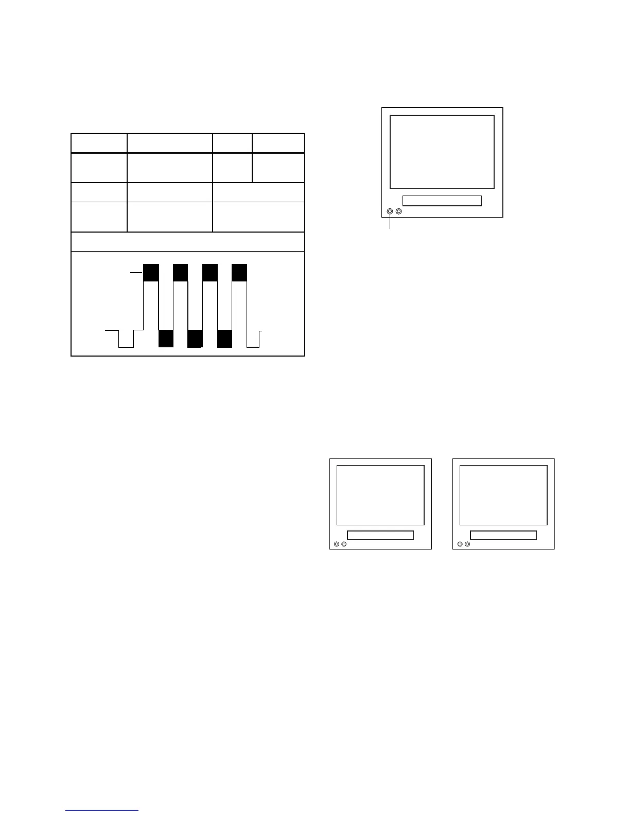
1. Connect Oscilloscope to J349F3.
2. Input a color bar signal from RF (or Ext.) input.
Enter the Service mode. (See page 1-6-10.)
3. Press [0] button on the remote control unit and
select C-TRAP Mode.
4. Press [P+/P-] buttons on the remote control unit so
that the carrier leakage B-Out (4.43MHz) value
becomes minimum on the oscilloscope.
5. Turn the power off and on again.
4. How to measure the standard
V-ENV value of Digital Studio
Picture Control
Purpose: To set the recording condition appropriate
for the recording tape.
Symptom of Misadjustment: Recording or playing
back picture quality may fall. The picture will be tinted.
1. Insert a new tape (type: E180) for the DSPC align-
ment into the TV/VCR.
2. Input the black raster signal from the video input
jack (VIDEO-IN).
3. Enter the Service Mode. (See page 1-6-10.)
4. To enter the DSPC mode, press [1] button on the
remote control unit. Recording starts automatically
and “DSPC” appears on the display.
5. Recording continues for 10 seconds in SP mode.
Note: Since the reference value of LP V-ENV is
computed from the reference value of SP V-ENV,
there is no need to survey it.
6. The tape is rewinded to the recording start point.
7. The unit enters the play mode automatically and
the V-ENV levels of each the reference value of SP
mode and the computing value of LP mode are
memorized into the EEPROM.
8. "OK" or "NG" appears on upper left corner of the
screen with blueback.
In case of "OK": "OK" (green) is indicated without
ejecting tape.
In case of "NG": "NG" (red) is indicated with eject-
ing tape.
l
Test point Adj. Point Mode Input
J349F3
(B-OUT)
P+/P-
buttons
RF
(or Ext.)
Color Bar
Tape M. EQ. Spec.
---
Oscilloscope,
Pattern Generator
200mVp-p Max.
Figure
minimum
Fig. 1
DSPC
VIDEO INPUT JACK (Ext. input)
TVCR
Fig. 2
NG
Abnormal
OK
Normal
TVCR TVCR
Fig. 3
 Loading...