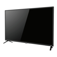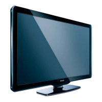
Do you have a question about the Philips 42PFL4606H/58 and is the answer not in the manual?
Outlines essential safety regulations for servicing the TV set.
Highlights critical warnings regarding ESD, high voltage, and tool usage during repair.
Details the procedure for removing the rear cover of the TV set.
Provides step-by-step instructions for removing the SSB.
Details the process for removing the power supply unit.
Details the steps for safely removing the LCD panel from the TV.
Introduces the four service modes: SDM, SAM, CSM, and ComPair.
Explains SDM purpose, specifications, activation, and on-screen menu.
Details SAM purpose, specifications, activation, and the on-screen menu.
Describes CSM purpose, specifications, and how to activate it.
Introduces ComPair as a diagnostic and repair tool for Philips TVs.
Introduces ComPair as a diagnostic and repair tool for Philips TVs.
Explains the possibility of upgrading TV software via the USB port.
Details the procedure for updating the TV software using a USB flash drive.
Lists specific error codes and their meanings, like I2C bus errors.
Introduces using blinking LED patterns for error identification when OSD is not working.
Provides general tips for troubleshooting and repairing the TV set.
Provides initial troubleshooting steps for a TV with no picture.
Suggests checking HDMI EDID data programming via ComPair for unstable pictures.
Advises checking HDCP key validity in CSM for no picture via HDMI.
Suggests checking Stand-by Controller failure and re-flashing software.
Emphasizes checking the Display Code in CSM after SSB replacement.
Guides on using SAM mode for software alignments like White point.
Describes the procedure to set the display option code using a specific key sequence.
Details the critical process of resetting the NVM on a repaired SSB.
Illustrates the power architecture and voltage distribution within the TV.
Details the audio amplifier IC and its I2S interface connections.
Highlights the MT5135AE's DVB-T/C demodulation, CI+ controller, and features.
Explains the MT5395's mini-LVDS output to the TCON-less panel.
Displays the block diagram and pin configuration of the TMDS351PAG HDMI input IC.
Shows the block diagram and pin configuration for the STA339BWTR audio amplifier IC.
Displays the block diagram and pin configuration for the TPA6132A audio amplifier IC.
Shows the block diagram and pin configuration of the MAX9668ETP TCON chip.
Displays the block diagram and pin configuration of the TPS65192RHDR TCON chip.
Shows the block diagram and pin configuration of the MAX17113ETL TCON chip.
Displays the block diagram and pin configuration of the G5172R41D power supply IC.
Circuit diagram for the SSB POWER-1 module.
Circuit diagram for the HDMI input interfaces, including EDID EEPROM and ESD protection.
Circuit diagram for the audio amplifier and headphone output stages.
Circuit diagram for TCON chip functions and pin configurations.


 Loading...