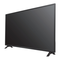
Do you have a question about the Philips 55PFL8008K/12 and is the answer not in the manual?
Essential safety regulations for repairs and post-repair checks.
Important warnings related to the device's operation or repair.
Instructions for removing internal assemblies and the display panel.
Discusses using test patterns via ComPair for diagnostic purposes.
Overview of Service Default Mode (SDM), Service Alignment Mode (SAM), and Customer Service Mode (CSM).
Explains the television's startup sequence and state transitions.
Information on service tools like ComPair, which is no longer supported.
Details error code logging, display, and clearing procedures.
Explains the procedure for identifying errors via LED blinking.
Covers software protections related to supplies and safety checks.
Provides guidance on general fault finding, including NVM initialization and options.
Describes how to upgrade the main and standby software via USB.
Specifies conditions like power supply voltage and warm-up time for adjustments.
Details how to set picture settings and adjust white point for LCD screens.
Discusses the power supply unit as a black box for service.
Shows the overall block diagram of the chassis architecture.
Illustrates the power supply lines and voltage distribution within the chassis.
Circuit diagram and PWB layout for the SSB (Single Side Band) module.
Circuit diagram and PWB layout for the 310431366185 SSB module.
Circuit diagram for the amplifier panel.
Circuit diagram for the amplifier module (Master/Slave 500KC).
Circuit diagram for the QFHD sensor board.
Circuit diagram for Wireless LAN, USB module, light sensor, IR/LED.
Circuit diagram for the light sensor and 3D IR components.
Circuit diagram illustrating power supply components.
Circuit diagram for the main microprocessor.
Circuit diagram for the light sensor and 3D IR components.
| Screen Size | 55 inches |
|---|---|
| Display Technology | LED |
| Resolution | 1920 x 1080 pixels |
| Smart TV | Yes |
| HDMI Ports | 4 |
| USB Ports | 3 |
| Wi-Fi | Yes |
| Audio Output | 20 W |
| 3D | Yes |
| Ambilight | Yes |
| Refresh Rate | 400 Hz |
| Digital TV Tuner | DVB-T/T2/C/S/S2 |
| Bluetooth | No |
| Ethernet | Yes |


 Loading...