Circuit Descriptions
EN 20 TPS15.3A LA7.
2015-Oct-23
back to
div.table
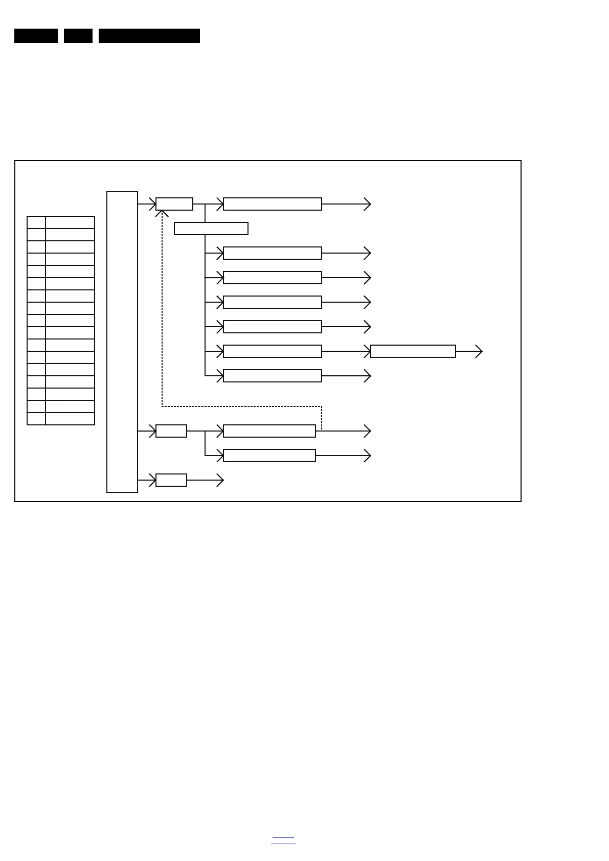
7.3 DC/DC Converters
The on-board DC/DC converters deliver the following voltages
(depending on set execution):
• +5VSB, permanent voltage for the Stand-by controller
• 3V3_STB, power supply for LED/IR receiver and Keyboard
• +12V, input from the power supply for the panel common
(active mode)
• P24V, input from the power supply for the amplifier
• DDR_1V5, supply voltage for DDR
• 5V_USB input supply voltage for WIFI
• +TU_3V3, supply voltage for tuner
• USB_5V, input intermediate supply voltage for USB Power
• 3V3_STB from the power supply for the scaler IC
MSD8590QV
Figures gives a graphical representation of the DC/DC
converters with its current consumptions:
Figure 7-3 DC/DC converters [1] (6600 series)
12V
12V
GND
16
15
14
U702 AZ1117D
VCC_1V2_CPU
Max. 6A
Max. 6A
VCC_1V2
U704 G5196R41D
DDR_1V5
U707 AT1528P11U
Max. 2A
U705 G5196R41D
4
24V
Power Board Input : +5VSB, P12V, P24V
10
3
POWER
BOARD
5
GND
Q705 AO4449-7A
12V
VCC_5V
Function
GND
7
5.2V
24V
5.2V
PWR_ON
12V
12
6
2D_3D *
DIM
11
1
2
13
Pin
8
+5VSB
GND
9
BL_ON_OFF
U701 AP1117E33L-13-77
Max. 1A
3V3_STB
VCC_1V8
U706 AP1117E18G-13
Max. 0.6A
TU_3V3
VCC_3V3
Max. 1A
USB_5V
P24V
Q403 AO4449-7A
U703 G5312QN1UP12V
PANEL LVDS Power
Audio Amplifier
Max. 6A
U708 AZ1117D
Max. 1A
U709 AP1117E33L-13-77
Max. 1A
19980_202.eps
 Loading...