Mechanical Instructions
EN 13TPL16.1E LA 4.
2016-Sep-23
back to
div.table
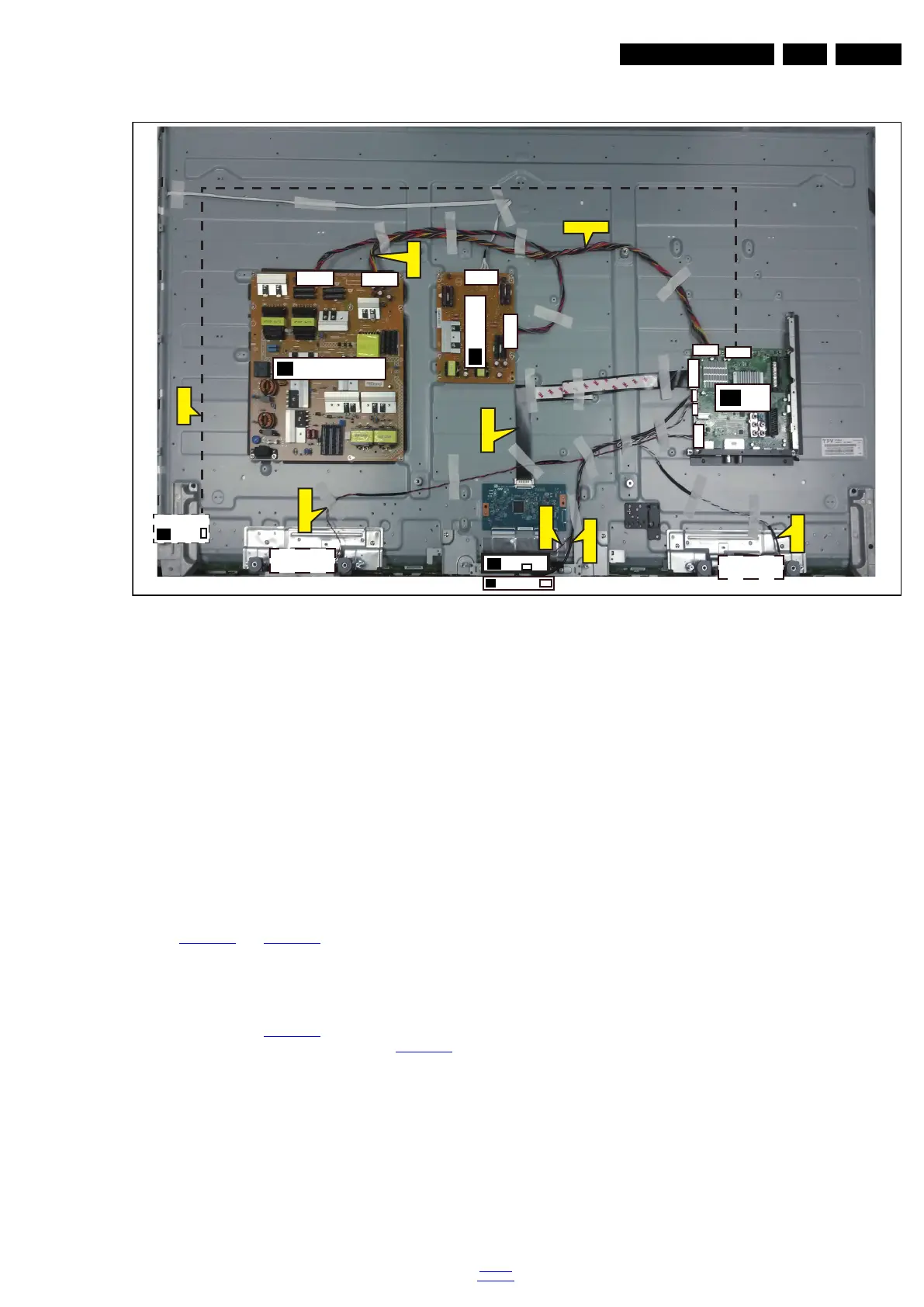
Figure 4-6 Cable dressing (65" 6121 series)
4.2 Service Positions
For easy servicing of a TV set, the set should be put face down
on a soft flat surface, foam buffers or other specific workshop
tools. Ensure that a stable situation is created to perform
measurements and alignments. When using foam bars take
care that these always support the cabinet and never only the
display. Caution: Failure to follow these guidelines can
seriously damage the display!
Ensure that ESD safe measures are taken.
4.3 Assembly/Panel Removal(for 6101 & 6121
series)
Instructions below apply to the 43PUS6101/12, but will be
similar for other 43"/49"/55"/65"Pxx61x1 series models.
4.3.1 Rear Cover
Refer to Figure 4-7
and Figure 4-8 for details.
Warning: Disconnect the mains power cord before removing
the rear cover.
1. Remove fixation screws [1] that secure the base assy, pull
out the base assy from the set.
2. Remove the fixation screws [2], [3] and [4] that secure the
rear cover. Refer to Figure 4-7
for details.
3. Unplug the connector [5] from SSB. Refer to Figure 4-8
for
details.
4. Gently lift the rear cover from the TV. Make sure that wires
and cables are not damaged while lifting the rear cover
from the set.
20112_102.eps
CN601
CN4605
CN401
CN9101
CN701
CN408
MAIN POWER SUPPLY
(1054)
A
IR/LED BOARD
(1056)
J
SSB
(1053)
B
ECN701
ECN4605
ECN408
ECN601
ECN701
ECN412
ECN601
ECN601
LOUDSPEAKER
(1184)
LOUDSPEAKER
(1184)
CN1
CN8602
CN8601
CN9201
KEYBOARD CONTROL
(1057)
E
CN01
CN412
WIFI MODULE
W
WiFi01
LED DRIVER
(1055)
AD
 Loading...