EasyManua.ls Logo

Philips AZ1008 Service Manual

Philips AZ1008
24 pages
To Next Page IconTo Next Page
Page #1 background imageLoading...
Page #1 background image
CLASS 1
LASER PRODUCT
GB
3140 785 22520Published by SS 0052 Service Audio
or otherwise without the prior permission of Philips.
system or transmitted, in any form or by any means, electronic, mechanical, photocopying,
All rights reserved. No part of this publication may be reproduced, stored in a retrieval
Copyright 1995 Philips Consumer Electroncis B.V. Eindhoven, The Netherlands
be used.
condition and that parts which are identical with those specified
Safety regulations require that the set be restored to its original
C
PCS 107 163
Printed in The Netherlands Copyright reserved Subject to modification
CD Stereo Radio Recorder
TABLE OF CONTENTS
chapter
Handling chip components and safety 1 - 1
AZ1008
.............................
Technical Specification & Service Tools 2 - 1
..........................
Service Measurement 2 - 2
..................................................
Connections & Controls
3 - 1
................................................
Instructions for use
3 - 2 to 3 - 4
.................................................
Block Diagram
4 - 1
.............................................................
Wiring Diagram 5 - 1
............................................................
circuit diagram
6 - 1
.......................................................
FRONT BOARD
layout diagram
6 - 1
........................................................
circuit diagram
7 - 1, 7 - 3
...................................................
COMBI BOARD
layout diagram
7 - 2, 7 - 4
...................................................
chapter
circuit diagram
8 - 1
.......................................................
TUNER BOARD
layout diagram
8 - 2
.......................................................
circuit diagram
9 - 1
.......................................................
REOCRDER BOARD
layout diagram 9 - 2
.......................................................
cabinet
10 - 1
.................................................................
EXPLODED VIEW DIAGRAM
tape deck
10 - 2
............................................................
Mechanical partslist
10 - 2
.....................................................
Electrical partslist
11 - 1 to 11 - 3
...............................................
all versions

Other manuals for Philips AZ1008

Question and Answer IconNeed help?

Do you have a question about the Philips AZ1008 and is the answer not in the manual?

Philips AZ1008 Specifications

General IconGeneral
TypeCD Player
BrandPhilips
ModelAZ1008
Playback FormatsCD, CD-R, CD-RW
Power SupplyAC/DC
AntennaFM Antenna
Audio Playback ModesFast Forward/Backward, Next/Previous Track Search, Repeat Play
Tuner BandsFM
Speaker diameter3 inch
Battery typeC size
Power Supply AC220V

Summary

Handling Chip Components

General Handling Procedures

General guidance for handling sensitive electronic components like ICs and semiconductors.

Chip Component Dismounting

Techniques and tools for safely removing surface-mount electronic components.

Chip Component Mounting

Best practices for placing and soldering surface-mount components onto PCBs.

Handling Precautions

Essential precautions to prevent damage to components during repair.

Component Handling Examples

Visual examples illustrating correct and incorrect methods for handling electronic parts.

Technical Specifications

General Specifications

Basic technical details including mains voltage, power consumption, and physical dimensions.

Amplifier Specifications

Details on output power and speaker impedance for the amplifier section.

Tuner FM Section Specifications

Performance metrics for the FM tuner, including tuning range and sensitivity.

Tuner AM Section Specifications

Performance metrics for the AM tuner, including tuning range and sensitivity.

Audio Cassette Recorder Specifications

Technical data for the cassette playback and recording functions.

Compact Disc Specifications

Performance data for the CD playback functionality.

Service Tools List

Recommended tools and test discs for servicing the audio unit.

ESD Protection Equipment

List of equipment available for electrostatic discharge protection during repairs.

Service Measurements

Tuner FM Measurement Setup

Procedure and equipment for measuring the performance of the FM tuner.

Tuner AM Measurement Setup

Procedure and equipment for measuring the performance of the AM tuner.

CD Measurement Setup

Method for testing CD player functionality using specific test discs.

Recorder Measurement Setup

Procedure and equipment for measuring the performance of the tape recorder.

Connections and Controls

Top and Front Panel Controls

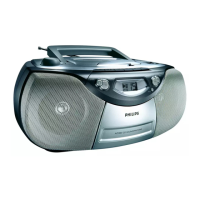
Identification and function of all buttons, knobs, and displays on the unit's front and top.

Back Panel Connections

Details of ports and connectors located on the rear of the appliance.

Power Supply Operation

Information on using AC mains power versus battery power for the unit.

Instructions for Use

Radio Reception Guide

Steps for tuning and receiving radio broadcasts on AM and FM bands.

CD Player Operation

Guide to using CD playback features like track selection, repeat, and programming.

Cassette Recorder Operation

Instructions for cassette playback, recording, and program erasure.

Recording Procedures

Instructions for recording audio from the CD player or radio onto cassette tape.

Troubleshooting Common Issues

Solutions for common problems encountered with the device's operation.

Block Diagram

Wiring Diagram

Front Board

Front Board Circuit and Layout Diagrams

Schematic and component placement diagrams for the front board assembly.

Combi Board

Combi Board Control/CD Part Circuit Diagram

Schematic detailing the control and CD sections of the Combi board.

Combi Board Solder Side Layout Diagram

Component placement illustration for the solder side of the Combi board.

Combi Board Circuit Diagram (Part 2)

Additional schematic views for the Combi board's circuitry.

Combi Board Component Side Layout Diagram

Component placement illustration for the component side of the Combi board.

Loudspeaker Board

Loudspeaker Board Circuit and Layout Diagrams

Schematic and component placement for the loudspeaker board.

CD Door Switch

CD Door Switch Circuit and Layout Diagrams

Schematic and placement details for the CD door switch mechanism.

Tuner Board ATM5

Tuner Board ATM5 Circuit Diagram

Schematic diagram of the ATM5 Tuner board.

Tuner Board ATM5 Layout Diagram and Adjustments

Component layout and tuning adjustment procedures for the Tuner board.

Recorder Board

Recorder Board Circuit Diagram

Schematic diagram of the Recorder board.

Recorder Board Layout Diagram and Adjustments

Component layout and adjustment procedures for the Recorder board.

Exploded View Diagram - Cabinet

Mechanical Parts

Cabinet Mechanical Parts List

List of mechanical components for the unit's cabinet assembly.

Tape Deck Exploded View Diagram

Visual breakdown of the tape deck mechanism and its parts.

Tape Deck Mechanical Parts List

List of mechanical components specific to the tape deck mechanism.

Electrical Parts List

Front Board Electrical Parts

List of electronic components and their part numbers for the front board.

Main Board Electrical Parts

List of electronic components and their part numbers for the main board.

Miscellaneous Electrical Parts

List of general electronic components not specific to a single board.

Tuner Board ATM5 Electrical Parts

List of electronic components and their part numbers for the Tuner Board ATM5.

Recorder Board Electrical Parts

List of electronic components and their part numbers for the Recorder Board.

Related product manuals