INSTALLATION
WARNING: TO PREVENT HIGH VOLTAGE FROM BEING PRESENT ON RED & YELLOW OUTPUT
LEADS PRIOR TO INSTALLATION, INVERTER CONNECTOR MUST BE OPEN. DO NOT JOIN
INVERTER CONNECTOR UNTIL INSTALLATION IS COMPLETE AND AC POWER IS SUPPLIED TO
THE EMERGENCY BALLAST.
NOTE: Make sure the necessary branch circuit wiring is available. An unswitched source of
power is required. The emergency ballast must be fed from the same branch circuit
as the AC ballast.
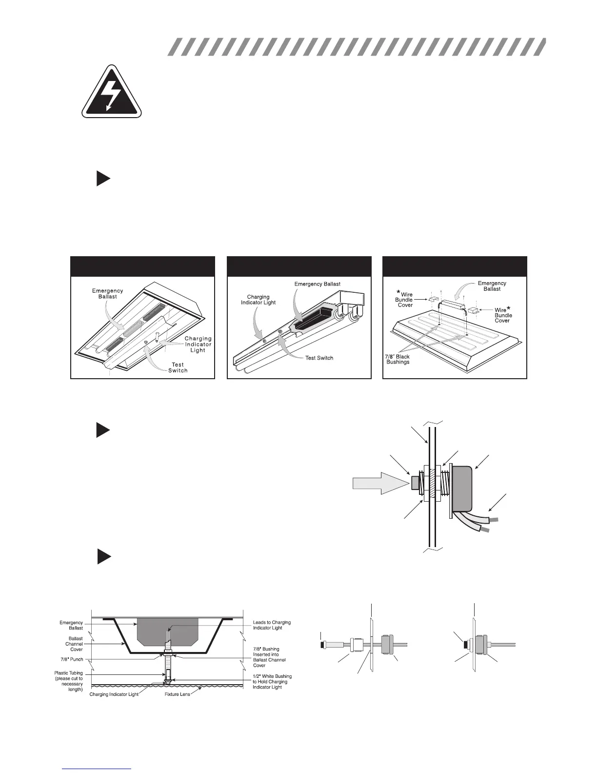
STEP #1
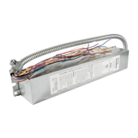
INSTALLING THE EMERGENCY BALLAST
> Disconnect AC power from the xture. Remove the ballast channel cover and install the emergency ballast
either in the ballast channel or on top of the xture.* Remote mounting distance must be less than half the
maximum remote mounting distance for the AC ballast. Consult AC ballast manufacturer before remote
installation.
> Depending on the type of xture in use install emergency ballast using one of the methods illustrated below.
STEP #2
INSTALLING THE TEST SWITCH
> Refer to the illustrations above and install the test switch
through the ballast channel cover of a troffer or through the
side of a strip xture.
> Drill a 1/2" hole and install the switch as shown.
> Refer to the diagrams on page 4 and wire the test switch so
that it removes AC power from the unswitched hot line to the
emergency ballast.
* For installation on top of the xture, wire bundle covers (RMC-60) may be required by state or local codes. These covers are
available from the manufacturer as an accessory kit and must be ordered separately. Call your local distributor or the factory for complete
information.
Inside Ballast Channel
Inside Strip Fixture
On Top of Fixture
INSIDE BALLAST CHANNEL INSIDE STRIP FIXTURE ON TOP OF FIXTURE
Fixture
Test Button
Hex Nut
Hex Nut
Test Switch
Leads
Push to Test
STEP #3
INSTALLING THE CHARGING INDICATOR LIGHT
> Install the CHARGING INDICATOR LIGHT as shown in the illustration on the next page so that it will be visible
after the xture is installed.
2
NOTE: After installing the charging indicator light and test switch, mark each with the appropriate label.
TROFFER STYLE FIXTURE
STRIP STYLE FIXTURE
Charging
Indicator
Light
1/2" White
Bushing
Violet (+)
Brown (–)
Violet (+)
Brown (–)
1/2" White
Bushing
5/8" Black
Bushing
5/8" Black
Bushing
1/2" Punch
Fixture
Fixture
Charging
Indicator
Light
* If violet and brown leads are detached, connect to
unit by matching wire colors.