STEP #1
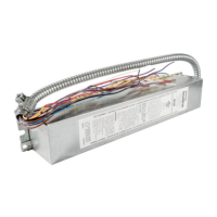
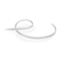
INSTALLING THE EMERGENCY BALLAST
as shown. Remote mounting distance must be less than half the
maximum remote mounting distance of the AC ballast. Consult
AC ballast manufacturer before remote installation.
On Top of Fixture
WARNING: TO PREVENT HIGH VOLTAGE FROM BEING PRESENT ON RED & YELLOW OUTPUT
LEADS PRIOR TO INSTALLATION, INVERTER CONNECTOR MUST BE OPEN. DO NOT JOIN
INVERTER CONNECTOR UNTIL INSTALLATION IS COMPLETE AND AC POWER IS SUPPLIED
TO THE EMERGENCY BALLAST.
as the AC ballast.
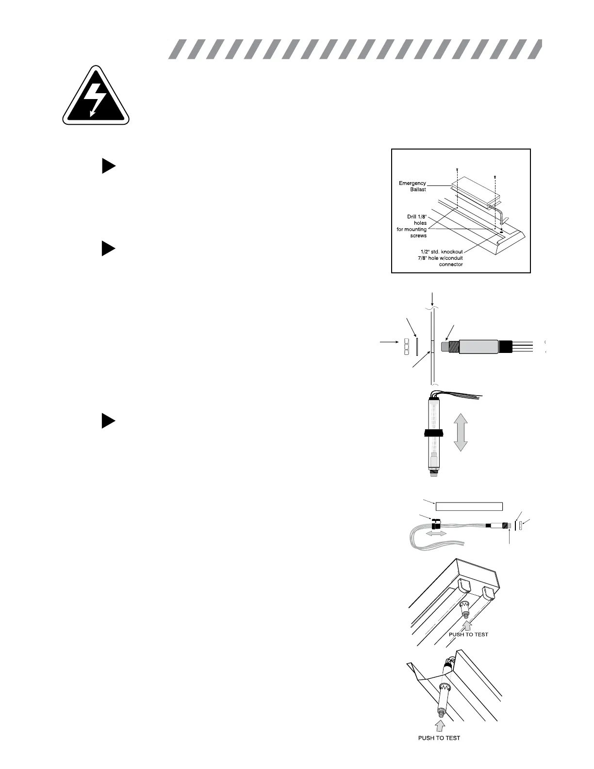
STEP #2a
INSTALLING THE ITS ON WALL PLATE OR
FIXTURE SURFACE
that it removes AC power from both the emergency ballast
and the AC ballast at the same time.
Lock
Washer
Hex Nut
Illuminated
Test Switch
Fixture or
Test/Monitor Plate
Violet
Black
Brown
Black
Drill or Punch
a 3/8” Hole
Plastic Tube
Washer
Indicator Light/Test Switch
Hex Nut
Strain Relief
Bushing
INSTALLING THE ITS ON THE BALLAST
CHANNEL COVER
ibility of the charging indicator light.
length.
tighten.
STEP #2b
2
INSTALLATION