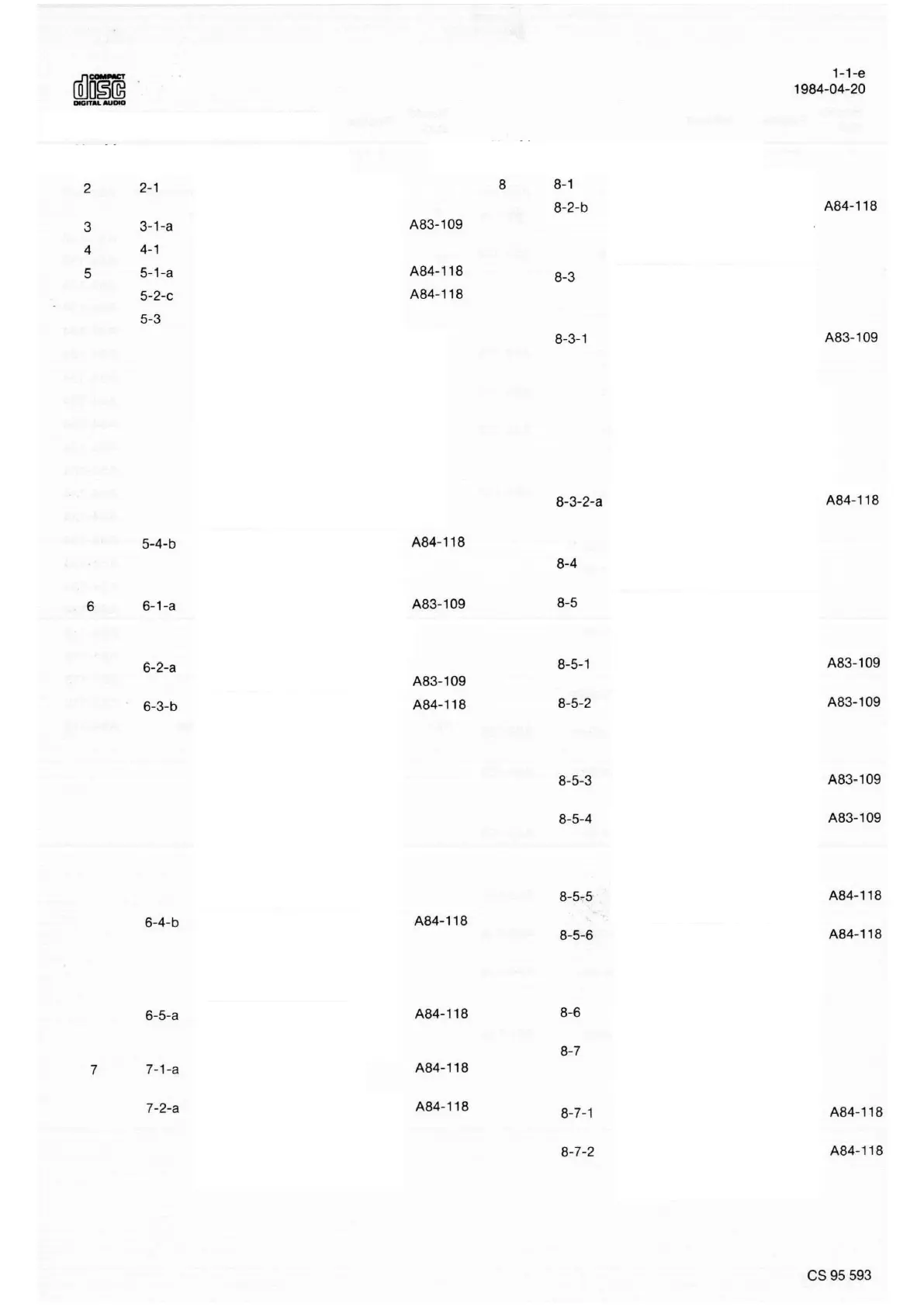
1. TABLE OF CONTENTS PER PAGE
Explanation of the layout of the
Documentation
Bill Of Materials - Tools
Replacing the Transformer Fuse
Servicing the Mains Input Filter
Servicing the Decoding Board
Servicing the Servo Board
Servicing the Switch and Display Board
Replacing the LED Board
Replacing the Turntable Motor
Replacing the Lid
Service of the RAFOC unit
Turntable Height Adjustment
Checking the Angle Setting
Adjusting the Angle Setting
Measurement Specification
Changing the Transformer
Connections
Adjusting the Offset Control
Control of the A.G.C. and Offset
circuits
Adjusting the Channel Equality
Setting of the PLL Circuit
Laser Power Control and
Adjustment (NEG.VOLT.PH.)
Adjusting the Focus Bandwidth
Laser Power Control and
Adjustment (POS.VOLT.SH.)
Exploded view of the Cabinet
BOMs
Exploded View of the Frame
Exploded view of the
mechanism/parts list
Mains Filter Circuit Schematic
Mains Filter PCB Drawing
BOM
Power Supply Circuit Schematic
Power Supply PCB Drawing
BOM
Power Supply Circuit Schematic
Power Supply PCB Drawing
BOM
6V Power Supply Circuit Schematic
6V Power Supply PCB Drawing
BOM
Power Supply Circuit Schematic
BOM
Pre-amplifier Circuit Schematic
Pre-amplifier PCB Drawing
BOM
Pre-amplifier Circuit Schematic
Pre-amplifier Circuit Schematic
Pre-amplifier PCB Drawing
(NEG.VOLT PH.)
BOM
Pre-amplifier PCB Drawing
(POS.VOLT.SH.)
BOM
Pre-amplifier Circuit Schematic
Pre-amplifier PCB Drawing
(POS. VOLT. SH.)
BOM
Control Circuit Schematic
Control Circuit Schematic