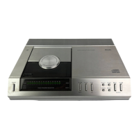
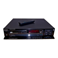
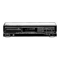
Removing the frame
• Remove the bottom plate after removing the 5 screws at the bottom.
• Turn the player over.
• The top cover can now be lifted and turned forward.
• To be able to take measurements of the device, the lid must be closed
(the power supply for the laser diode is via the lid switch).
• When measuring at the bottom of the frame, make sure that the device is
not resting on the turntable motor shaft.
NOTE: Before closing, the power switch must be in the "ON" position.
Replacing the transformer fuse
• Take the frame out of the cabinet.
• Remove the transformer shield at the top of the frame, after the two
locking tabs have been bent away.
Servicing the secondary filter PCB
• Take the frame out of the cabinet.
• Remove the transformer shield at the top of the frame, after the two
locking tabs have been bent away.
• Remove the 2 screws in the transformer shielding on the underside of the
frame.
• The shield can be dismantled after the locking clip has been bent away
from the PCB.
Servicing the decoding board and the servo board
• Take the frame out of the cabinet.
• Remove the 2 metal protective plates at the top of the frame.
• Remove the 2 screws from the decoder board.
• By placing the decoding board in one of the two service
positions (see Fig.), measurements can be made on both the
decoding board and the servo board.
• If the servo PCB has to be removed from the frame, remove
the metal shielding plate at the bottom of the frame.
• The PCB can be removed after removing the 6 fixing screws: 4
screws are mounted in the PCB of the cooling block. These are
accessible from the rear of the frame.
Servicing the switch and display board
• The PCB is mounted in the top cover.
Remove the top cover, (see "removing the frame")
• The PCB is accessible from the track side.
• If the PCB needs to be detached, remove the 5 fixing screws.
Replacing a LED
• Remove the switch and display PCB from the top cover (see
"service of the switch and display PCB")
• Remove the indication plate above the LEDs after removing
the two fixing screws in the PCB.
• The LED holder consists of two parts which are attached to
each other with 4 locking tabs.
The upper part of the LED holder can be removed by bending
away the 4 locking tabs.
• The LED can be removed upwards from the PCB.
• When mounting, pay attention to the correct connection (anode
and cathode) and the height of the LED: To get the LED to the
correct height, it must be pushed against the top of the LED
holder before soldering.
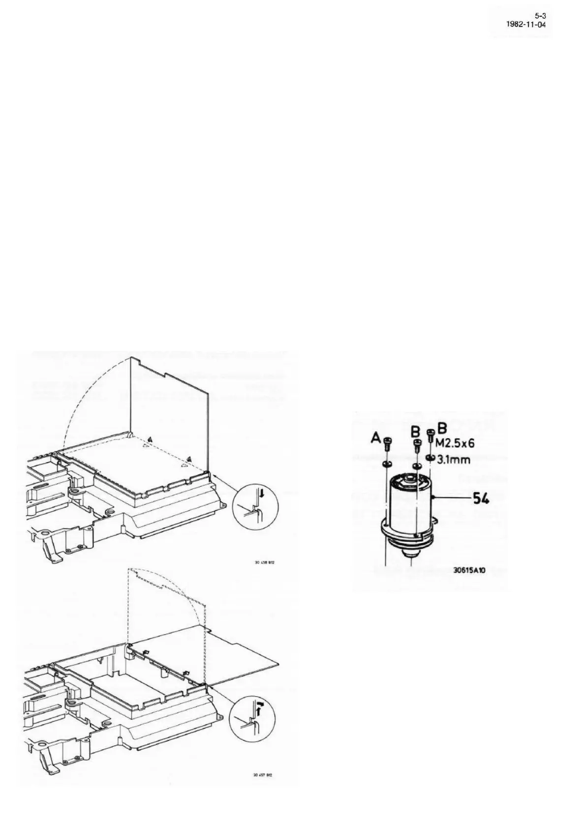
Replacing the rotary table motor
• Take the frame out of the cabinet.
• Remove the preamplifier board which is attached to the CD
mechanism with four screws
• The turntable motor is attached to the chassis plate with 3
screws.
• When mounting, screw A must first be mounted (see Fig.).
ATTENTION: After assembly, the motor must be checked as
follows:
a. CD/Plate-light angle
b. Height adjustment of the turntable
 Loading...