1-7-1 E7E4ADC
CABINET DISASSEMBLY INSTRUCTIONS
1. Disassembly Flowchart
This flowchart indicates the disassembly steps to gain
access to item(s) to be serviced. When reassembling,
follow the steps in reverse order. Bend, route, and
dress the cables as they were originally.
2. Disassembly Method
Note:
(1) Identification (location) No. of parts in the figures
(2) Name of the part
(3) Figure Number for reference
(4) Identification of parts to be removed, unhooked,
unlocked, released, unplugged, unclamped, or
desoldered.
P = Spring, L = Locking Tab, S = Screw,
CN = Connector
* = Unhook, Unlock, Release, Unplug, or Desolder
e.g. 2(S-2) = two Screws (S-2),
2(L-2) = two Locking Tabs (L-2)
(5) Refer to “Reference Notes.”
Reference Notes
1. CAUTION 1: Locking Tabs (L-1) and (L-2) are
fragile. Be careful not to break them.
ID/
Loc.
No.
Part
Removal
Fig.
No.
Remove/*Unhook/
Unlock/Release/
Unplug/Desolder
Note
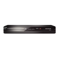
[1] Top Cover D1 6(S-1) ---
[2]
Front
Assembly
D2
*5(L-1), *3(L-2),
*CN1061, Shield A
1
[3] SW CBA D2 *2(L-3),*CN1063 ---
[4]
Power SW
CBA
D2 (S-2) ---
[5]
DVD
Mechanism
& DVD Main
CBA
Assembly
D3
4(S-3), (S-4), (S-5),
*CN101, *CN701,
Locking Card
Spacers,
M-PCB Plate Earth
---
[6]
Power
Supply CBA
D4 4(S-6), *CN1060 ---
[7] Rear Panel D5
(S-7), 6(S-8), 2(S-9),
Fan Holder
---
[8] AV CBA D5
5(S-10), DV Jack,
DV Earth Plate
---
[9]
Front
Bracket
D5
2(S-11), (S-12), (S-13)
M-PCB Plate Earth
---
↓
(1)
↓
(2)
↓
(3)
↓
(4)
↓
(5)
[3] SW CBA
[4] Power SW CBA
[2] Front Assembly
[1] Top Cover
[6] Power Supply CBA
[7] Rear Panel
[9] Front Bracket
[5] DVD Mechanism &
DVD Main CBA Assembly
[8] AV CBA
[1] Top Cover
(S-1)
(S-1)
(S-1)
Fig. D1

 Loading...