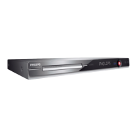
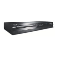
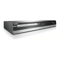
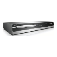
Figure 3 – Unscrew the screws to detach front panel
Figure 4 - Front Panel Service Position
Insulation Sheet Insulation Sheet
1.3. Dismantling of the Basic Engine
1) Remove 4 mounting screws mounting the Basic Engine1007 from the Frame Assembly 0920 as shown in
figure 5.
Figure 5 - Basic Engine mounting screw
2) Flip the Basic Engine over to remove 4 screws from the PCB protection plate. Service Position of the Basic
Engine is shown in Figure 6.
 Loading...
