EasyManua.ls Logo

Philips dynalite User Manual

Philips dynalite
23 pages
To Next Page IconTo Next Page
Page #1 background imageLoading...
Page #1 background image
16
th
February 2022 www.philips.com/dynalite
Electrical &
Hardware
Installation Guide
Installing the Data Network
A Do NOT connect DALI or mains power to DyNet data terminals.
1. The data cable is connected to all devices as per the project
schematic following correct color code and DyNet terminations.
Devices may be wired in any order.
2. The recommended connection method is to ‘daisy chain’ devices in sequence, starting at the first device,
then looping in and out of each device, with a single cable terminating at the last device. There should
not be any branching, and only the first and last device should terminate a single cable, all other devices
should terminate two cables.
3. A data cable that is connected to an energized device is live. Do not cut or terminate live data cables.
4. The cable tail can be returned to the original distribution board. Ground wire and power wire (+V) can be
connected in a loop but D+ and Dmust NOT be connected in a loop. Do not connect power wire (+V) in
a loop where segmentation is required between network sections that have multiple power supplies
deployed, to ensure Network cable current limits are not exceeded.
5. Maximum allowed power supply rating and data cable current for any section of the network is the
lowest of either 2 Amps or the Cable rating per local wiring code or cable manufacturer specification.
Where required, apply power wire (+V) segmentation per network design to prevent exceeding limits. Use
only approved DyNet power supplies to ensure network reliability and safety.
6. The data cable should be segregated from mains cables by a minimum of 50 mm (2 in) for shielded cable
and 300 mm (12 in) for unshielded cable or as per local wiring code specification (whichever is greater).
If the data cable crosses over any mains cables, it should cross at 90°, whilst maintaining correct
segregation. The wiring segregation distance may be reduced if either data cables, mains cables or both
are fitted in separate grounded metal conduits.
7. On Button Panels and Sensors, the Shield wires must be terminated into the shield terminal. Shield wires
are automatically earthed on each controller. For controllers that do not have a shield terminal, the shield
should be twisted together and taped to the cable sheath to maintain continuity.
8. The maximum recommended length for DyNet cables between two
network bridges is 800 m (2620 ft). For cable runs over 300 m (1000 ft),
(or baud rates over 9600 bps), 120 Ohm, 2 W end-of-line resistors must
be installed across the D+ and D- terminals of the DyNet connector
strip on the first and last devices.
Question and Answer IconNeed help?

Do you have a question about the Philips dynalite and is the answer not in the manual?

Philips dynalite Specifications

General IconGeneral
CategoryControl Systems
Product NameDynalite
Network ProtocolEthernet
User InterfaceTouchscreens, keypads, web interface, mobile apps
ManufacturerPhilips
Control MethodCentralized
CompatibilityDALI
Power Supply24V DC
Operating Temperature0°C
Humidity Range10% to 90% non-condensing
DimensionsVaries depending on device type (e.g., controllers, power supplies, user interfaces)
WeightVaries depending on device type

Summary

Data Network Installation Guide

Data Cable Termination Procedures

Recommended DyNet Cable Types

Device Limits on Cable Runs

Standard Cable Terminations

Alternative Control Cable Types

1-10V cabling

Explains 1-10V cabling using mains rated polarized cabling, typically a "figure-8" cable.

DALI Cabling Specifications

DALI Network Topology

DALI Broadcast

Describes DALI broadcast topology requiring individual wiring for each lighting group.

DALI Addressable

Explains DALI addressable bus wiring to enumerated drivers, supporting up to 64 addresses.

DALI with multi-master

Covers DALI wiring for enumerated drivers and multi-master devices like sensors.

Load Controller Installation

DALI Controllers

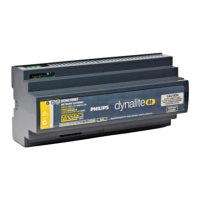
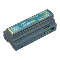
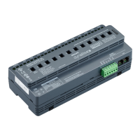
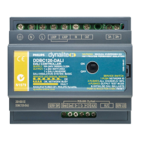
Details DALI controller specifics, including DALI bus cabling, driver limits, and power supply.

System Installation Examples

Gateway Installation and Configuration

User Interface Installation

Sensor Installation and Placement

Motion detection positioning

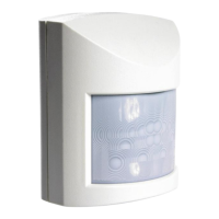
Guides on positioning sensors for optimal motion detection, considering environmental factors.

Light regulation positioning

Details sensor placement for closed and open loop light regulation methods.

Dry Contact Input Device Installation

DLL18180 and DPMI940-DALI

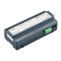
Covers installation of DALI dry contact input devices DLL18180 and DPMI940-DALI.

DDMIDC8

Details installation of the DDMIDC8 analog input device, including jumper settings.

System Energizing and Testing

Power-up tests

Outlines procedures for testing the system after power-up, including button and service switch functions.

Controller Service Switch functions

Explains the functions of controller service switches, including reset and test modes.

Controller Service LED functions

Describes the signaling modes of the controller service LED (normal, network activity, communication, fault).

Troubleshooting and Fault Finding

DyNet bus issues

Lists steps for troubleshooting DyNet bus issues, starting with symptom analysis.

Electrical characteristics

Details electrical properties like supply voltages, data voltages, and current limits for DyNet.

Unresponsive devices

Provides a procedure to isolate faults in unresponsive devices by breaking the network into halves.

DALI Bus Troubleshooting

Advanced DALI troubleshooting

Explains advanced DALI troubleshooting using oscilloscopes, covering signal edges and voltage levels.

General Troubleshooting Tables

Load Controller Issues

Provides a table of probable causes and solutions for load controller issues.

Device Specific Troubleshooting

Touchscreen issues

Lists symptoms, probable causes, and solutions for touchscreen malfunctions.

Third-Party System Integration

Related product manuals