Dynalite Hardware
.......................................
Installation Guide
.......................................
Page 13
.......................................
16
th
February 2022 www.lighting.philips.com/dynalite
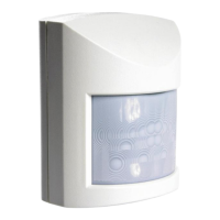
Installing sensors
Motion detection positioning
A single Dynalite sensor can perform motion detection, light regulation and IR receive simultaneously.
Typical detection range is measured at ≤25°C (77°F).
Range is reduced at ambient temperatures above 32°C (90° F)
Sensors must receive specified supply voltage 15 V or 24 V ± 10% from the DyNet network. If necessary, add a
network power supply to ensure adequate network voltages are maintained during day to day fluctuations.
Ensure the 2 A limit is not exceeded on any data cabling.
Position sensor to detect motion in the specified area:
1. Install correct sensor type for location and application (wall or ceiling mounted, PE, PIR, ultrasonic, high
bay, outdoor). Ensure DUS 30/90/AHB/WHB/LHB sensors go to the correct locations.
2. Ensure correct orientation for long and short field of view.
3. Install sensor out of direct sunlight.
4. Install sensors away from air conditioning vents and sources of electromagnetic interference.
5. Except for ultrasonic detection, avoid obstructions when installing sensors,
6. Lift inbuilt mask where applicable, to limit sensor detection area.
Lights trigger only upon entry Using detection area mask May trigger from passersby
For detailed information, refer to the sensor positioning guide on Dynalite.org.