Do you have a question about the Philips FR965/00 and is the answer not in the manual?
Setup for measuring tuner performance using RF generators and voltmeters.
Essential safety regulations and component marking guidelines for repairs.
Risks of electrostatic discharge (ESD) to semiconductors and handling precautions.
Guidelines for safely dismounting, mounting, and soldering chip components.
Instructions for connecting the receiver to the mains power supply.
Guide for connecting front, surround, and center speakers.
Procedure for adjusting speaker volumes and testing sound output.
Recommendations for optimal placement of front, center, and surround speakers.
Overview of the menu system, options, and how to navigate through them.
Settings for subwoofer, center, and rear speaker presence.
Adjusting speaker sizes (SMALL/LARGE) and listening distances.
Assigning audio input connectors to different source selections.
Explanation of surround sound effects and compatible formats like Dolby Digital, DTS, MPEG.
How to cycle through and activate different surround sound modes.
How to search for and tune into radio stations by scanning or direct frequency input.
Procedures for automatically or manually programming radio stations into memory.
Initial settings for speakers (size, distance) for optimal surround sound.
Step-by-step guide to remove the front panel assembly.
Visual flowchart guiding through the service test program sequence.
Details on performing key tests like tuner, display, and temperature tests.
References to adjustment table, block diagram, component layout, and circuit diagram.
Procedure for aligning the varicap circuit for optimal FM, MW, LW reception.
Steps for adjusting FM detection and VCO for accurate tuning.
Procedure to minimize distortion in the FM tuner section.
Alignment procedures for the AM Intermediate Frequency and Radio Frequency stages.
Steps for diagnosing and resolving issues with the MDM module.
Schematic representation of the MDM module's internal signal flow.
Schematic diagram of the mains power supply board.
Visual guide to components on the mains board.
Detailed circuit diagram for the main power supply board.
Diagram showing the primary and secondary connections of the mains transformer.
Component placement diagram for the mains board.
Copper trace layout diagram for the mains board.
Test points and expected voltages for IC7643 on the MONO2 board.
Test points and expected voltages for IC7504 on the MONO2 board.
Test points and functionality for IC7641 on the MONO2 board.
Test points and functionality for IC7642 on the MONO2 board.
Circuit diagrams for the amplifier sections (front, surround).
Circuit diagrams for the front, left, right, and center amplifier channels.
Circuit diagrams for the surround amplifier channels.
| Brand | Philips |
|---|---|
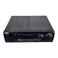
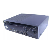
| Model | FR965/00 |
| Category | Stereo Receiver |
| Language | English |