EasyManua.ls Logo

Philips FW-C28/34 User Manual

Philips FW-C28/34
72 pages
To Next Page IconTo Next Page
Page #1 background imageLoading...
Page #1 background image
PCS 103 329
Service
Service
Service
FW-C30/21/21M/30/37
TABLE OF CONTENTS
Page
Location of pc boards & Version variations ................1-2
Technical Specifications .............................................1-3
Measurement setup ....................................................1-4
Service Aids, Safety Instruction, etc...........................1-5
Instruction for use: USA version excerpt ..................2-1
Additional features for /21 ...... 2-10
Disassembly Instructions & Service positions ...........3-1
Service Test Programs ...............................................3-4
Set Block diagram ......................................................... 4
Set Wiring diagram ........................................................ 5
Front Board .................................................................... 6
Tuner Board: ECO5 Sys .......................................... 7B
ECO MTF Module .......................................................... 9
3CDC 99 Module ......................................................... 10
Combi Board ................................................................ 11
Set Mechanical Exploded view & parts list ................. 12
©
Copyright 1999 Philips Consumer Electronics B.V. Eindhoven, The Netherlands
All rights reserved. No part of this publication may be reproduced, stored in a retrieval system or
transmitted, in any form or by any means, electronic, mechanical, photocopying, or otherwise
without the prior permission of Philips.
Published by KC 9948 Service Audio Printed in The Netherlands Subject to modification
GB
3139 785 22120
CLASS 1
LASER PRODUCT
COMPACT
DIGITAL AUDIO
Mini System
FW-C3/37 & FW-C35/37
Service Manual
Question and Answer IconNeed help?

Do you have a question about the Philips FW-C28/34 and is the answer not in the manual?

Philips FW-C28/34 Specifications

General IconGeneral
BrandPhilips
ModelFW-C28/34
CategoryStereo System
LanguageEnglish

Summary

Location of PC Boards

Version Variations

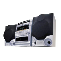
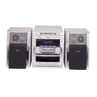
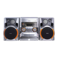
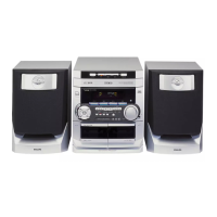
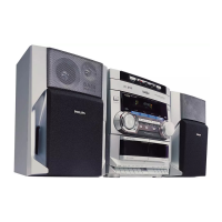
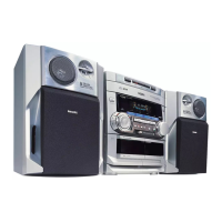
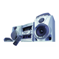
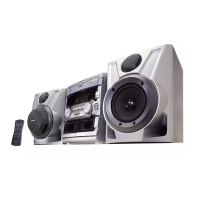
Details variations across different system models based on features.

Specifications

General Specifications

Covers mains voltage, frequency, power consumption, clock accuracy, and dimensions.

Amplifier Specifications

Details output power, frequency response, and input sensitivity.

Tuner Specifications

Lists FM, MW, and LW tuning ranges, IF frequencies, and sensitivity.

Cassette Recorder Specifications

Outlines track count, tape speed, wow/flutter, and frequency response.

Compact Disc Specifications

Provides details on frequency response, output level, and signal-to-noise ratio.

Measurement Setup

Tuner FM Measurement Setup

Describes the setup for measuring FM tuner performance using specific equipment.

Tuner AM (MW, LW) Measurement Setup

Details the measurement setup for AM tuners, including Faraday cage use.

CD and Recorder Measurement Setup

Outlines setups for measuring CD playback and recorder performance.

Service Aids and ESD Protection

Service Tools and Equipment

Lists essential tools and ESD protection equipment for repairs.

Cassette and CD Test Aids

Lists specific test cassettes and discs for diagnostics.

ESD Handling and Safety Warnings

ESD Handling Precautions

Explains susceptibility of ICs and semiconductors to ESD and handling requirements.

Laser Product Safety Warning

Warns about invisible laser radiation when the unit is open.

General and Safety Information

General Information Details

Covers system typeplate, environmental aspects, and supplied accessories.

Safety Information and Precautions

Advises on voltage checks, repair warranty, and moisture condensation.

Preparation and System Connections

Antenna Connections

Instructions for connecting AM loop and FM wire antennas.

Speaker and Subwoofer Connections

Guides on connecting front/rear speakers and an optional subwoofer.

External Equipment and Power Connections

How to connect external sources, AC power, and insert remote batteries.

System Controls and Operation

System Controls Overview

Details buttons and functions on the main unit and remote control.

System Operation Modes

Covers demonstration mode, easy set, and source selection.

CD Operations

CD Playback and Changer Loading

Explains CD playback modes, loading the changer, and changing discs.

Sound and Display Controls

Covers DIM mode, sound controls like DSC and DBB.

CD Operations - Advanced Functions

Track Selection and Programming

How to select tracks, search passages, and program playback sequences.

Program Review and Erasing

Procedures for reviewing or clearing programmed track sequences.

Tuner Tuning and Presets

Instructions for tuning radio stations and storing presets.

Tape Operations

Tape Loading, Playback, and Rewind

Guides on inserting tapes and starting playback on tape decks.

Continuous Tape Playback

How to play tapes continuously from one deck to another.

Recording Functions

Recording Notes and One Touch Recording

General recording notes and how to start recording with one button.

CD Synchro Start and Tape Dubbing

Procedures for recording CDs to tape and dubbing tapes.

System Timers and Clock

Recording from Other Sources

Details on recording audio from sources like CD, Tuner, or AUX to tape.

Clock Display and Setting

How to view and set the system's clock in 12 or 24-hour format.

Timer and Sleep Timer Functions

Setting the system to turn on at a preset time or switch off automatically.

Maintenance and Troubleshooting

Maintenance Procedures

Guidelines for cleaning cabinet, discs, CD lens, and tape heads.

Troubleshooting Common Issues

Steps to resolve common problems like no system reaction or remote control failure.

CD Player and Radio Reception Troubleshooting

Diagnosing CD errors and improving radio reception.

Tape Deck and System Troubleshooting

Resolving tape deck issues and system malfunctions.

Additional Features

MW Tuning Grid and Karaoke Functions

Adjusting MW tuning and using the karaoke feature with microphone mixing.

Operating Voltage Adjustment

Instructions for setting the voltage selector before connecting power.

Dismantling Instructions

Cassette Cover and Front Panel Dismantling

Steps for removing the cassette cover and the main front panel.

Front Control and Assemblies Dismantling

Instructions for carefully removing front control covers and assemblies.

Dismantling Instructions - Rear and Speaker Units

Rear Portion and Loudspeaker Box Dismantling

Steps for disassembling the rear section and loudspeaker boxes.

Service Test Program

Tuner, Quartz, and Play Mode Tests

Procedures for performing tuner, quartz, and service play mode tests.

Various System Test Programs

Details on EEPROM, Encoder, and other system diagnostic tests.

Block Diagrams and Wiring

Set Block Diagram

Shows the overall functional block diagram of the system.

Set Wiring Diagram

Illustrates the electrical wiring connections throughout the system.

Front Board Details

FTD Display Pin Connections

Details the pin assignments for the FTD display.

Front Board Variation Table and Circuit Diagram

Lists variations and shows the electrical schematic for the front board.

Front Board Layouts and Parts List

Component, chip layouts, and electrical parts list for the front board.

Tuner Board ECO5 Details

Tuner Board ECO5 Block Diagram and Adjustments

Shows the block diagram and lists adjustment points for the ECO5 tuner board.

Tuner Board ECO5 Layout and Circuit Diagram

Illustrates component placement and provides the electrical schematic for the ECO5 tuner board.

Tuner Board ECO5 Parts List

A comprehensive list of parts used on the ECO5 tuner board.

Tuner Board 95 Details

Tuner 95 Board Block Diagram and Adjustments

Shows the block diagram and lists adjustment points for the Tuner 95 board.

Tuner 95 Board Layout and Circuit Diagram

Illustrates component placement and provides the electrical schematic for the Tuner 95 board.

Tuner 95 Board Parts List

A list of all parts used on the Tuner 95 board.

ECO MTF Module Details

ECO MTF Module Block Diagram and Circuit Diagram

Shows the block diagram and electrical schematic for the ECO MTF module.

ECO MTF Module Component Layout and Adjustments

Illustrates component placement and lists adjustment points for the ECO MTF module.

ECO MTF Module Exploded Views and Parts List

Shows exploded views and lists electrical parts for the ECO MTF module.

3CDC 99 Module Overview

3CDC Module Demounting and Servicing Hints

Guidance on safely disassembling and servicing the 3CDC module.

3CDC Module Lubrication and ESD Warnings

Details lubrication points and specific ESD warnings for the 3CDC module.

3CDC Module Diagrams and Lists

Covers block diagrams, wiring, circuit diagrams, layouts, and parts lists for the 3CDC module.

Combi Board Overview

Combi Board Introduction and Features

General introduction and feature configuration table for the Combi board.

Combi Board Main Part Layouts

Component and chip layouts for the main section of the Combi board.

Combi Board Circuit Diagrams

Circuit diagrams for Source Select, Amplifier, Power Supply, and Transformer sections.

Combi Board Karaoke, CDC Key, and Headphone Sections

Circuit and layout diagrams for Karaoke, CDC Key, and Headphone parts.

Combi Board Electrical Parts List

A comprehensive list of electrical components used on the Combi board.

Exploded View - Main Unit

Mechanical & Accessories Parts List - Main Unit

Mechanical & Accessories Parts List

Lists mechanical and accessory parts for the main unit.

Screw Lists - Main Unit

A list of screws used in the main unit assembly.

Loudspeaker Box Breakdown

Details the parts breakdown for the loudspeaker boxes.

Related product manuals