Do you have a question about the Philips FW-V330/21M and is the answer not in the manual?
Technical specifications for audio and video performance of VCD/CD playback.
Technical specifications for the amplifier, including output power and input sensitivity.
Lists specialized tools and ESD protection equipment required for servicing.
General warnings about ICs and semi-conductors susceptibility to ESD in multiple languages.
Warnings about invisible laser radiation when the unit is open, in multiple languages.
Test procedure for leakage current after servicing to ensure safety.
Steps to prepare the system, including rear connections and antenna/speaker setup.
Explains functions of system and remote control buttons for basic operations.
Controls for selecting tuner, tape, and auxiliary inputs.
Controls for CD/VCD tray, disc change, and video output selection.
Controls for Digital Sound Control, Jog control, and Dynamic Bass Boost.
Controls for playback modes, track navigation, and tuning.
Remote functions specific to VCD playback and operations.
General troubleshooting guide for common issues like no reaction, no sound, or reversed outputs.
Step-by-step instructions for dismantling the 3-disc CD changer module.
Instructions for dismantling the bottom and rear panel assembly.
Instructions for dismantling the front panel assembly.
Instructions for separating the MPEG and 3CDC-LC-VCD modules.
Table for tape adjustment and performance checks.
List of mechanical parts for the play mechanism.
List of mechanical parts for the record/playback mechanism (non-autoreverse).
List of mechanical parts for the record/playback mechanism (autoreverse).
Exploded view showing the assembly of the 3CDC-LC-VCD module.
Critical warnings regarding CD mechanism replacement and ESD protection.
Instructions for dismantling the CD tray.
Instructions for assembling the CD tray.
Component layout on the copperside of the PCB.
Exploded view of the drawer mechanism from the bottom.
Exploded view of the drawer mechanism from the top.
Details about the power supply circuit and its regulated voltages.
Details about source selection, amplification, and sound features.
Table for adjusting tuner parameters.
Table for adjusting tuner parameters for Cenelec versions.
| Bluetooth | Yes |
|---|---|
| USB Direct | Yes |
| Audio In | Yes |
| Number of Discs | 1 |
| Audio output power | 30 W |
| Output Power (RMS) | 30 W |
| Display | LCD |
| Disc Playback | CD, CD-R/RW |
| Tuner Bands | FM |
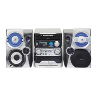
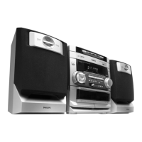
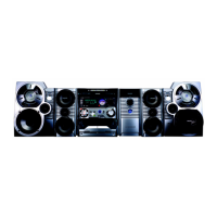
| Type | Mini Hi-Fi System |
| Supported Media | CD, USB |
| Product Type | Stereo System |
| USB Port | Yes |