EasyManua.ls Logo

Philips FWM462 User Manual

Philips FWM462
31 pages
To Next Page IconTo Next Page
Page #1 background imageLoading...
Page #1 background image
Version 1.0
FWM462
3141 785 35290
280W Mini Hi-Fi System
-/55/77/BK
Published by LX 1023 Service Audio Subject to modification
©
Copyright 2010 Philips Consumer Electronics B.V. Eindhoven, The Netherlands
All rights reserved. No part of this publication may be reproduced, stored in a retrieval
system or transmitted, in any form or by any means, electronic, mechanical, photocopying,
or otherwise without the prior permission of Philips.
CONTENTS
Technical specification ..................................................................1-2
Version variation ...........................................................................1-2
Service measurement setup..........................................................1-3
Service aids .................................................................................1-4
Instructions on CD playability ................................................2-1..2-2
Block diagram ................................................................................3-1
Wiring diagram ..............................................................................4-1
Disassembly diagram............ ................................................5-1..5-2
Main board
Circuit diagram .........................................................................6-1
Layout diagram ..................................................................6-2..6-3
AC board
Circuit diagram .........................................................................7-1
Layout diagram ..................................................................7-2..7-3
Display board
Circuit diagram .........................................................................8-1
Layout diagram ..................................................................8-2..8-3
AMP & Power Board
Circuit diagram. ........................................................................
9-1
Layout diagram ..................................................................
9-2..9-3
Tuner board
Circuit diagram .......................................................................10-1
Layout diagram .......................................................................10-2
CD Board
Circuit diagram. ......................................................................
11-1
Layout diagram ..............................................................
11-2..11-3
MCU Board
Circuit diagram. .............................................................
12-1..12-2
Layout diagram ..............................................................
12-3..12-4
Exploded view diagram ...............................................................13-1
All manuals and user guides at all-guides.com
all-guides.com
Question and Answer IconNeed help?

Do you have a question about the Philips FWM462 and is the answer not in the manual?

Philips FWM462 Specifications

General IconGeneral
Speaker type2-way
Audio amplifierYes
RMS rated power280 W
Woofer diameter133 mm
Tweeter diameter51 mm
Peak Music Power Output (PMPO)3600 W
TypeHome audio mini system
Cassette deckNo
Product colorBlack, Blue
Disc loading typeCarousel disc loader
Number of optical discs3 discs
Power sourceAC
Input voltage100-240 V
Input frequency50 - 60 Hz
Playback modesProgram, Repeat, Repeat all, Repeat one, Shuffle
Disc types supportedCD, CD-R, CD-RW
Playback disc formatsCD audio
Audio formats supportedMP3, WMA
Supported radio bandsFM, MW
Preset stations quantity40
USB direct modesFast Forward, Fast Backward, Play/Pause, Previous/Next, Program Play, Repeat, Shuffle, Stop
Display typeLCD
Weight and Dimensions IconWeight and Dimensions
Package depth316 mm
Package width1014 mm
Package height413 mm
Package weight15000 g
Main speaker width249 mm
Main speaker height344 mm
Main unit dimensions (WxDxH)265 x 403 x 310 mm

Summary

Technical Specification

Sound Specifications

Details audio output power, enhancement features, and speaker configuration.

Loudspeaker Configuration

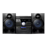
Describes the main speaker system and number of loudspeakers.

Audio Playback Features

Lists supported media formats and playback features for CD and USB.

Audio Recording Capabilities

Explains USB recording capabilities and sources.

Tuner and Reception Details

Covers tuning features, station presets, and band support.

Connectivity Options

Lists microphone sockets and other audio/USB connection types.

Convenience Features

Details alarm functions, clock display, and karaoke features.

Included Accessories

Lists included items like antennas, adaptors, and manuals.

Product Dimensions and Weight

Provides set and packaging dimensions, weight, and speaker size.

Power Supply Requirements

Specifies the power supply requirements.

Version Variation Overview

Shows how different board versions correspond to model variations.

Service Measurement Setup

FM Tuner Measurement Setup

Outlines the test setup for FM tuner measurements using RF generator and voltmeters.

AM Tuner Measurement Setup

Details AM tuner measurement setup, including Faraday cage use.

CD Playback Measurement Setup

Describes the test setup for CD playback measurements.

Recorder Measurement Setup

Specifies the test setup for recorder measurements.

Service Aids and Warnings

Electrostatic Discharge (ESD) Warning

Warns about electrostatic discharge (ESD) sensitivity of components.

Safety Component Identification

Mentions safety regulations and marking of safety components.

Lead-Free Soldering Information

Provides information on identifying and handling lead-free sets.

Post-Repair Service Instructions

Details critical points for returning the set to original condition after repair.

Instructions on CD Playability

CD Playback Troubleshooting (Set Closed)

Troubleshooting flowchart for CD playback issues when the set is closed.

Flap Loader Lens Cleaning Recommendation

Recommends cleaning method for flap loaders.

Customer Notification for OK Status

Suggests adding a note for customers when the set is OK.

CD Playability Verification Procedure

Details the procedure for checking CD playback compatibility.

Liquid Lens Cleaning Guide

Provides instructions for safely cleaning the CD lens.

Customer Information Guidelines

Advises on informing customers about checks and potential issues.

Block Diagram Overview

Wiring Diagram

Dismantling Instructions

CDC Module and Front Panel Disassembly

Step-by-step guide for disassembling the CD module and front panel.

Rear Portion Dismantling

Instructions for disassembling the rear part of the unit.

PCB Board Removal Procedures

Steps for removing specific PCB boards like AMP and USB.

Main Board Schematics and Layouts

Main Board Circuit Diagram

Electrical schematic of the main processing and control board.

Main Board Layout - Top Side

Component placement diagram for the top side of the main board.

Main Board Layout - Bottom Side

Component placement diagram for the bottom side of the main board.

AC Board Schematics and Layouts

AC Board Circuit Diagram

Electrical schematic of the AC power supply board.

AC Board PCB Layout

Component placement diagram for the AC board.

Display Board Schematics and Layouts

Display Board Circuit Diagram

Electrical schematic for the display and user interface board.

Display Board Layout - Top Side

Component placement diagram for the top side of the display board.

Display Board Layout - Bottom Side

Component placement diagram for the bottom side of the display board.

AMP Board Schematics and Layouts

AMP Board Circuit Diagram

Electrical schematic for the audio amplification board.

AMP Board Layout - Top Side

Component placement diagram for the top side of the amplifier board.

AMP Board Layout - Bottom Side

Component placement diagram for the bottom side of the amplifier board.

Tuner Board Schematics and Layouts

Tuner Board Circuit Diagram

Electrical schematic for the radio tuner circuit.

Tuner Board PCB Layout

Component placement diagram for the tuner board.

CD Board Schematics and Layouts

CD Board Circuit Diagram

Electrical schematic for the CD player control board.

CD Board Layout - Top Side

Component placement diagram for the top side of the CD board.

CD Board Layout - Bottom Side

Component placement diagram for the bottom side of the CD board.

MCU Board Schematics and Layouts

MCU Board Circuit Diagram - Part 1

Electrical schematic for the main control unit (MCU), Part 1.

MCU Board Circuit Diagram - Part 2

Electrical schematic for the main control unit (MCU), Part 2.

MCU Board Layout - Top Side

Component placement diagram for the top side of the MCU board.

MCU Board Layout - Bottom Side

Component placement diagram for the bottom side of the MCU board.

Exploded View Diagram

Related product manuals