GC8330
5-8
TRAY RUBBER CAP 37
BMC TRAY 36
STAND TOP 24
FRONT PANEL PRINTED 31
BOILER ASSY EE 20
ELECTROVALVE 21
POWER BOARD 35
CONTROL BOARD 41
PUMP ASSY 27
RINSE RUBBER COUPLING 38
RINSE BUSH 39
SAFETY CAP ASSY 29
REED SWITCH ASSY 33
Remove WATER TANK ASSY 42
Remove TRAY RUBBER CAP 37 (3x)
Remove Screws F1, F2, F3
Disassemble BMC TRAY 36
Remove Screws G1, G2, G3, G4
Remove SAFETY CAP ASSY 29
Remove RINSE BUSH 39
Remove RINSE RUBBER COUPLING 38
Disassemble STAND TOP 24
Remove Screws H1, H2
Disassemble BOILER ASSY 20
Remove Screws J1, J2
Disassemble FRONT PANEL PRINTED 31
K1
K2
K3
12 11
109
Pos. Connected to Pos. Connected to
9 Reed switch 11 Thermistor
10 Power board 12 Hosecord (Black)
Fig 5. Connections on CONTROL BOARD 41
DISASSEMBLY ADVICE - STAND & DETACHABLE WATER TANK
Remove Connections 9, 10, 11, 12 (Fig 5)
Remove Screws K1, K2, K3 (Fig 5)
Disassemble CONTROL BOARD 41
21
20
15
14
18
13
22
16
17
19
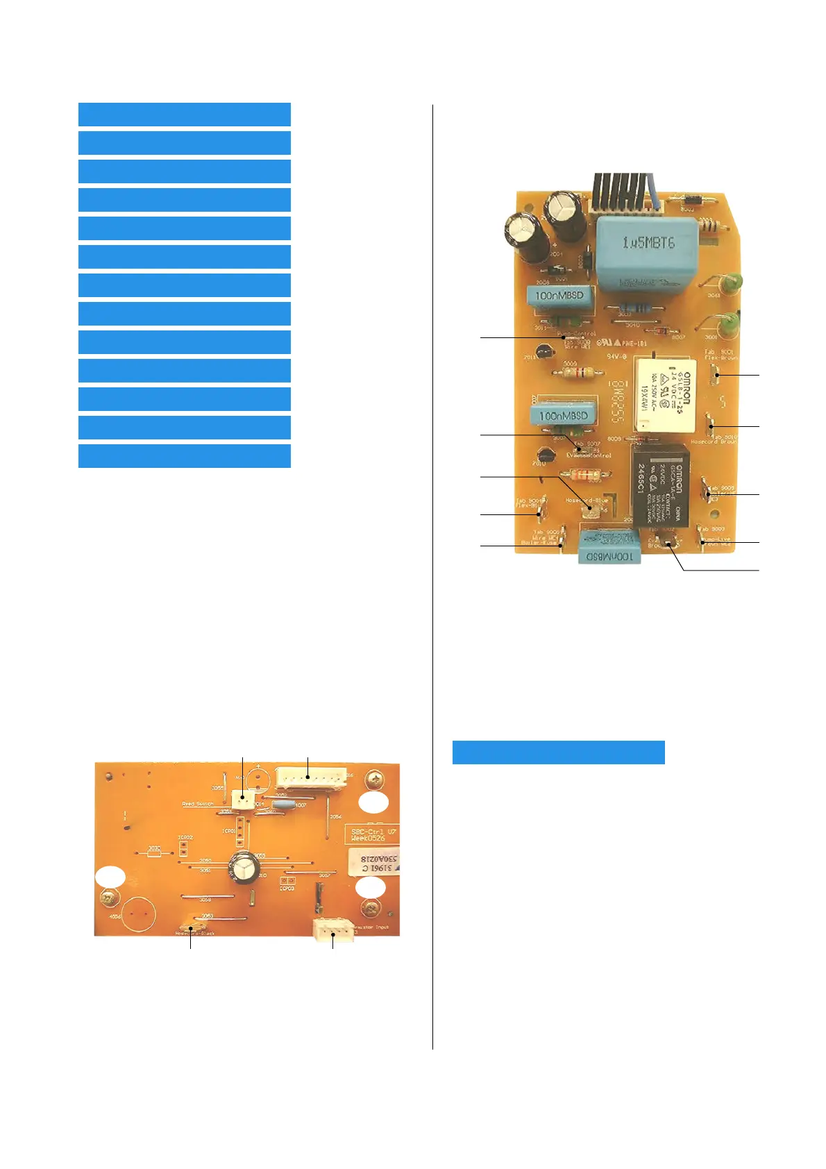
Pos. Connected to Pos. Connected to
13 Pump-Control 18 Electrovalve-Live
14 Pump-Live (Brown) 19 Hosecord (Blue)
15 Boiler-Heating Element 20 Hosecord (Brown)
16 Boiler-Fuse 21 Cordset (Brown)
17 Electrovalve-Control 22 Cordset (Blue)
Fig 6. Connections on POWER BOARD 35
WATER TANK ASSY 42