3 - 2 3 - 2
SERVICE POSITIONS
Service position A
Note:In some service positions the components or copper patterns of one board may risk touching its neighbouring pc boards or
metallic parts. To prevent such short-circuit use a piece of hard paper or other insulating material between them.
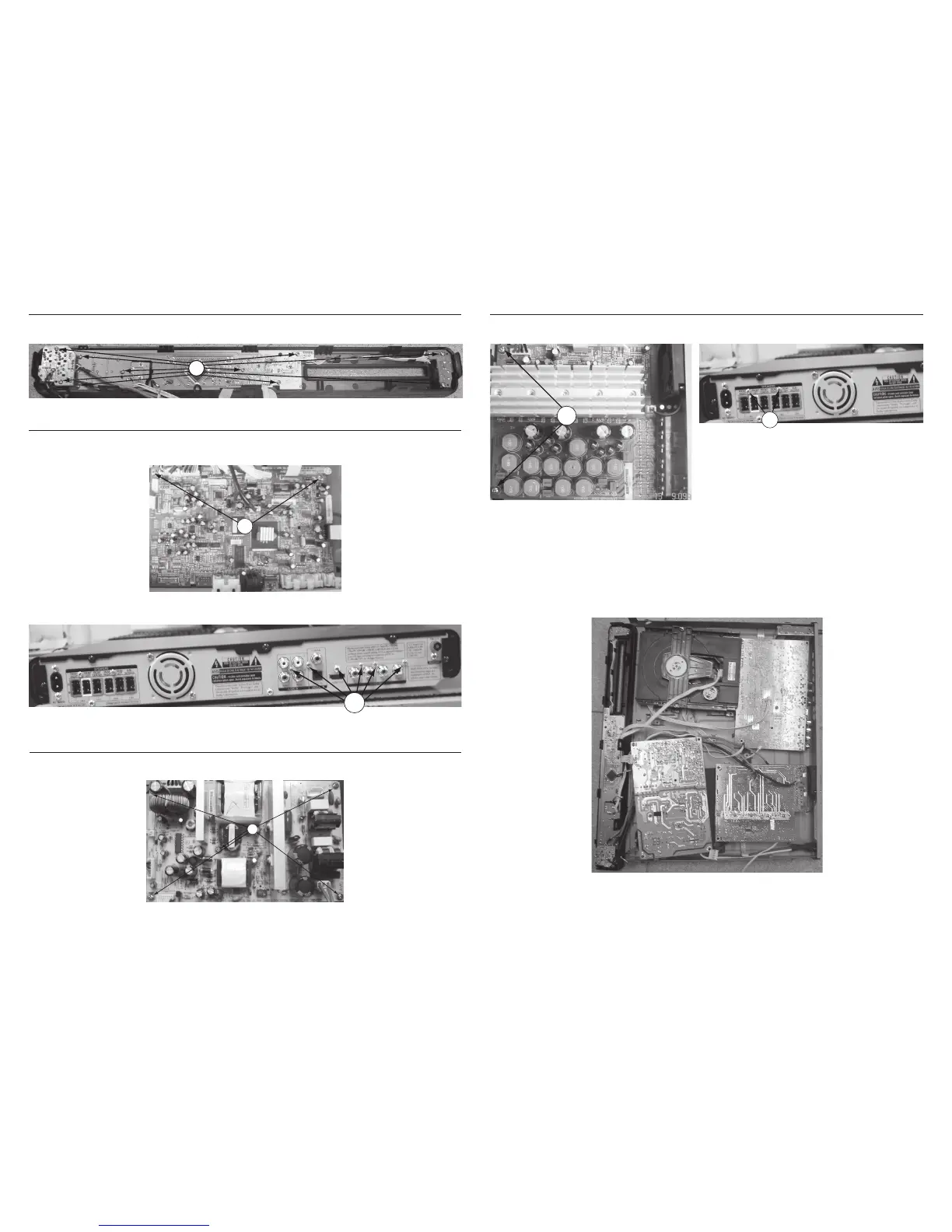
Dismantling of the Power Board
1) Loosen 5 screws “I” on the top of Power Board as shown in gure 12.
Figure 10
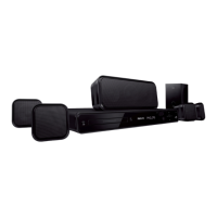
Dismantling of the VFD+JACK+VOL+STANDBY Board
1) Loosen 10 screws “F” on the top of VFD+JACK+VOL+STANDBY Board as shown in gure 9.
Figure 9
Dismantling of the Main Board
1) Loosen 2 screws “G” on the top of Main Board as shown in gure 10.
2) Loosen 6 screws “H“ at the back panel as shown in gure 11.
Figure 12
Figure 11
Dismantling of the AMP Board
1) Loosen 2 screws “J” on the top of AMP Board as shown in gure 13.
2) Loosen 2 screws “K“ at the back panel as shown in gure 14.