Do you have a question about the Philips HTS3571 and is the answer not in the manual?
Identifies the physical location of all Printed Circuit Boards within the system.
Details differences in features or specifications across different product versions.
Outlines repair strategies or component commonality across service types.
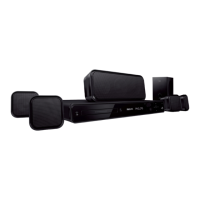
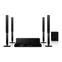
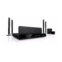
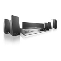
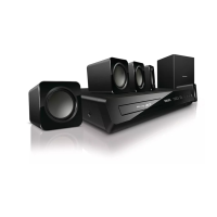
Lists detailed technical specifications for the DVD Home Theater System.
Describes procedures and equipment for measuring system performance.
Lists tools, discs, and materials required for service and repair tasks.
Provides guidelines for safely mounting and dismounting electronic chip components.
Explains precautions and requirements for handling components susceptible to static discharge.
Details guidelines and requirements for using lead-free solder in repairs.
Instructions for system reset, region code changes, and software upgrades.
Troubleshooting charts for diagnosing and repairing the main unit.
Step-by-step guide for disassembling the DVD Home Theater System.
Visual representation of the system's internal functional blocks and connections.
Illustrates the electrical connections between various components and boards.
Details the pin configuration and connections for the VFD display.
Electrical schematic for the VFD, Jack, Volume, and Standby board.
Component placement diagrams for the VFD board (top and bottom views).
Functional diagrams for key integrated circuits on the Main Board.
Electrical schematics for the Main Board (parts one and two).
Component placement diagrams for the Main Board (top and bottom views).
Functional diagrams for key integrated circuits on the Power Board.
Electrical schematic for the Power Board.
Component placement diagrams for the Power Board (top and bottom views).
Functional diagrams for key integrated circuits on the Amplifier Board.
Electrical schematic for the Amplifier Board.
Component placement diagrams for the Amplifier Board (top and bottom views).
Lists all parts used in the system with their corresponding part numbers.
| D/A converter | 12 bit, 108 MHz |
|---|---|
| Picture enhancement | High Def (720p, 1080i, 1080p), Progressive scan |
| Output power (RMS) | Front/Surround 4x170W, Centre/Subwoofer 2x250W |
|---|---|
| D/A converter | 24 bit, 192 kHz |
| Frequency response | 40-20000 Hz |
| Signal to noise ratio | >60 dB |
| Compression formats | MPEG1, MPEG2, DivX 3.11, DivX 4.x, DivX 5.x, DivX 6.0, DivX Ultra, WMV |
|---|---|
| Playback Media | DVD-Video, DVD+R/+RW, DVD-R/-RW, Video CD/SVCD, CD-R/CD-RW |
| Video disc playback system | NTSC, PAL |
| Compression format | MP3, WMA |
|---|---|
| Playback Media | CD |
| MP3 bit rates | 32-256 kbps and VBR |
| Power supply | 120/230VAC, 50/60Hz |
|---|---|
| Standby power consumption | < 1 W |
| Power consumption | 200 W |
| Satellite speaker drivers | 3" full range woofer |
|---|---|
| Satellite speaker impedance | 4 ohm |
| Satellite speaker freq range | 150-20000 Hz |
| Center Speaker | Magnetically shielded, 3 way |
| Center speaker drivers | 1 x 2" tweeter, 2 x 2.5" woofers |
| Center speaker impedance | 3 ohm |
| Center freq range | 150-20000 Hz |
| Subwoofer driver | 8" high efficiency woofer |
| Subwoofer impedance | 3 ohm |
| Subwoofer freq range | 40-150 Hz |
| Subwoofer type | Passive |
| Set dimensions (W x H x D) | 435 x 57 x 360 mm |
|---|---|
| Set weight | 3.69 kg |
| Surround Speaker dimensions (W x H x D) | 100 x 100 x 75 mm |
| Surround speaker Weight | 0.48 kg |
| Center speaker dimensions (W x H x D) | 440 x 105 x 75 mm |
| Center Speaker Weight | 1.43 kg |
| Subwoofer dimensions (W x H x D) | 163 x 352 x 360 mm |
| Subwoofer Weight | 5.76 kg |
| Packaging dimensions (W x H x D) | 555 x 391 x 514 mm |
| Weight incl. Packaging | 12 kg |