Mechanical Instructions
EN 11LC4.3E AA 4.
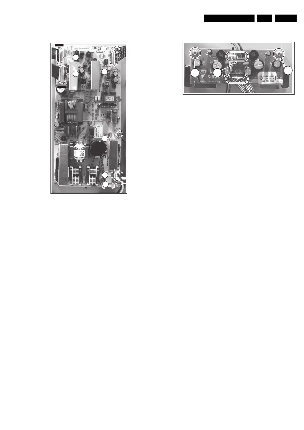
4.3.7 Power Supply Panel (various models used)
Figure 4-10 Power supply panel
1. Disconnect all cables (1) from the panel.
Notice that the two connectors for X520 and X530 on
this panel are similar, and should not be mixed up later
when they are reconnected (X520 is connected via its
flatcable to connector CN01 on the LCD panel, near the R-
speaker; X530 is connected via its flatcable to connector
CN04 on the LCD panel, near the L-speaker).
2. Remove the three fixation screws (2) from the panel.
3. Take the panel out of its brackets.
4.3.8 Audio Amplifier Panel
Figure 4-11 Audio amplifier panel
1. Disconnect all cables (1) from the panel.
2. Remove the fixation screws (2) from the panel.
3. Remove the panel.
F_15270_048.eps
180505
1
2
2
2
1
1
1
X530
X520
F_15270_049.eps
180505
1
2
2