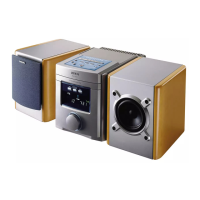
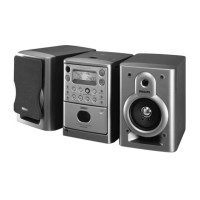
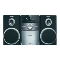
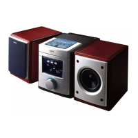
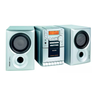
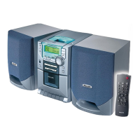
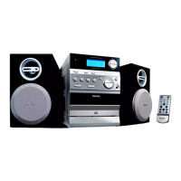
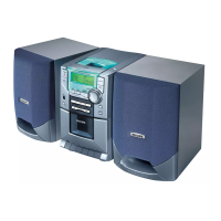
Micro System
all versions
Published by LX 0416 Service Audio Printed in The Netherlands Subject to modification
©
Copyright 2004 Philips Consumer Electronics B.V. Eindhoven, The Netherlands
All rights reserved. No part of this publication may be reproduced, stored in a retrieval
system or transmitted, in any form or by any means, electronic, mechanical, photocopying,
or otherwise without the prior permission of Philips.
Handling chip components ............................................................1-1
Technical specification...................................................................2-1
Service tools..................................................................................2-1
Service measurement setup..........................................................2-2
Connections and controls..............................................................3-1
Instructions for use.................................................................3-2..3-7
Disassembly diagram ....................................................................4-1
Service Test Program....................................................................4-2
Pin description of ICs..............................................................4-3..4-4
Set block diagram..........................................................................5-1
Set wiring diagram.........................................................................5-2
LED BOARD
circuit diagram ..........................................................................6-1
layout diagram ..........................................................................6-1
TUNER BOARD (ECO6 cenelec)
circuit diagram ..........................................................................7-1
layout diagram ..........................................................................7-2
tuner adjustment table ..............................................................7-2
TUNER BOARD (ECO6 non cenelec)
circuit diagram ..........................................................................7-3
layout diagram ..........................................................................7-4
tuner adjustment table ..............................................................7-4
MTF TAPE DECK MODULE
circuit diagram ..........................................................................8-1
layout diagram ..........................................................................8-2
tape deck adjustment................................................................8-2
circuit diagram(for /22 only)......................................................8-3
layout diagram(for /22 only)......................................................8-4
FRONT BOARD
circuit diagram ..........................................................................9-1
layout diagram..................................................................9-2...9-3
COMBI BOARD
circuit diagram. .............................................................10-1...10-3
layout diagram..............................................................10-4...10-5
CD MODULE (CD99-DA11)
circuit diagram ..............................................................11-1...11-3
layout diagram ........................................................................11-2
POWER BOARD
circuit diagram ........................................................................12-1
layout diagram ........................................................................12-1
Exploded view diagram (main set) ....................................13-1...13-2
Exploded view diagram (tape deck).............................................13-2
Mechanical partslist.....................................................................13-3
Electrical partslist ........................................................................13-3
Electrical partslist .............................................................14-1..14-16
(Not service parts,only for referrence)
TABLE OF CONTENTS