KEY & VFD BOARD
TABLE OF CONTENTS
FTD Display Pin Assignment........................................... 5-1
Circuit Diagram ................................................................5-2
PCB Layout Top & Bottom View ......................................5-3
Electrical Parts List .......................................................... 5-4
5-1 5-1
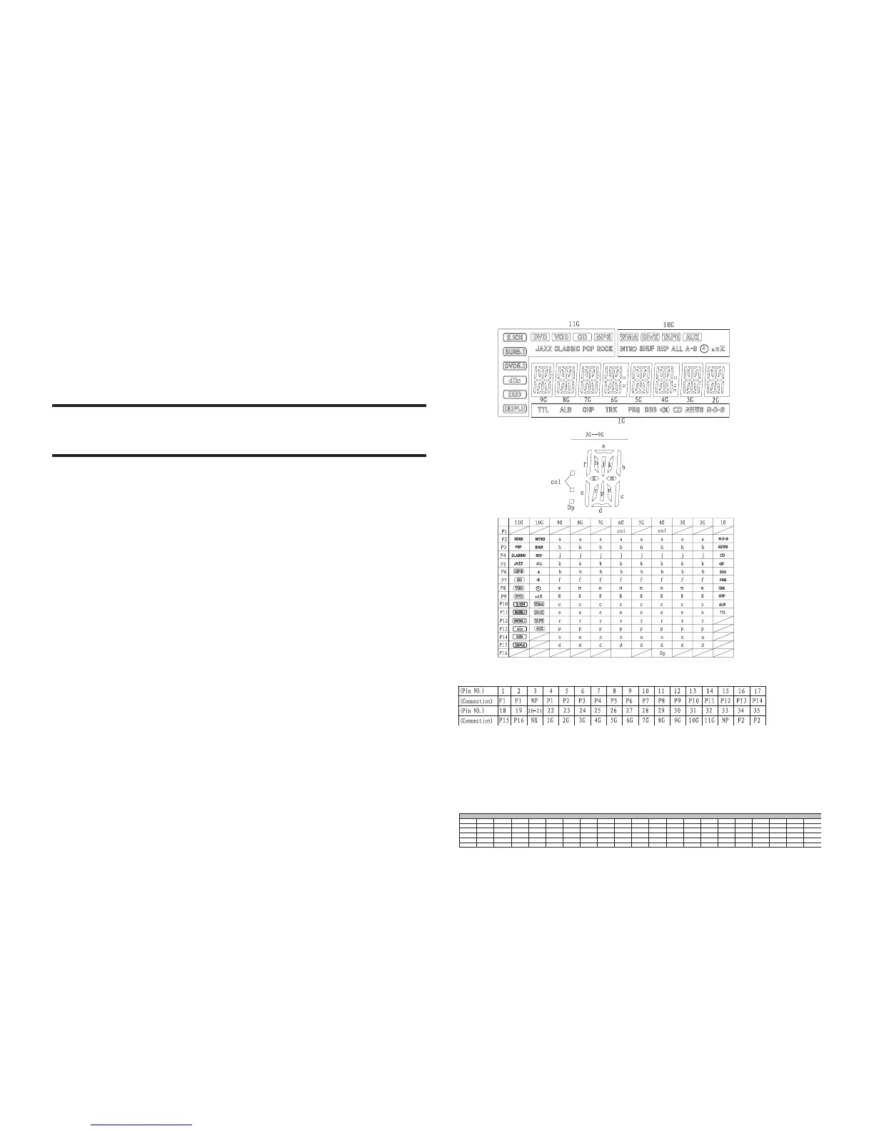
FTD DISPLAY PIN ASSIGNMENT
IC Pin Voltage
## Note ##
1. Fn: Filament pin
2. NP : No Pin
3. NX : No Extended Pin
4. nG : Grid Pin
5. PN : Anode Pin
Pin NO 1 2 3 4 5 6 7 8 9 10 11121314151617181920
Voltage 2.00 2.00 2.00 2.00 3.70 3.70 0.00 3.30 3.30 0.00 0.00 0.00 0.00 4.60 -21.7 -12.9 -20 -18.2 -21.8 -14.7
Pin NO 21 22 23 24 25 26 27 28 29 30 31 32 33 34 35 36 37 38 39 40
Voltage -12.6 -18.2 -20 -12.8 -12.8 -21.8 -18.5 -20 -13 -22.2 -20.5 -20.2 4.40 -22 -22.1 -20.2 -20.1 -20.1 -20 -20.1
Pin NO 41 42 43 44 45 46 47 48 49 50 51 52
Voltage -20.1 -20.2 -20.2 -20.3 4.40 4.40 44.00 4.40 4.40 4.40 0.00 2.30
IC200-PT6311(PTC)
PIN CONNECTION