5-1 5-1
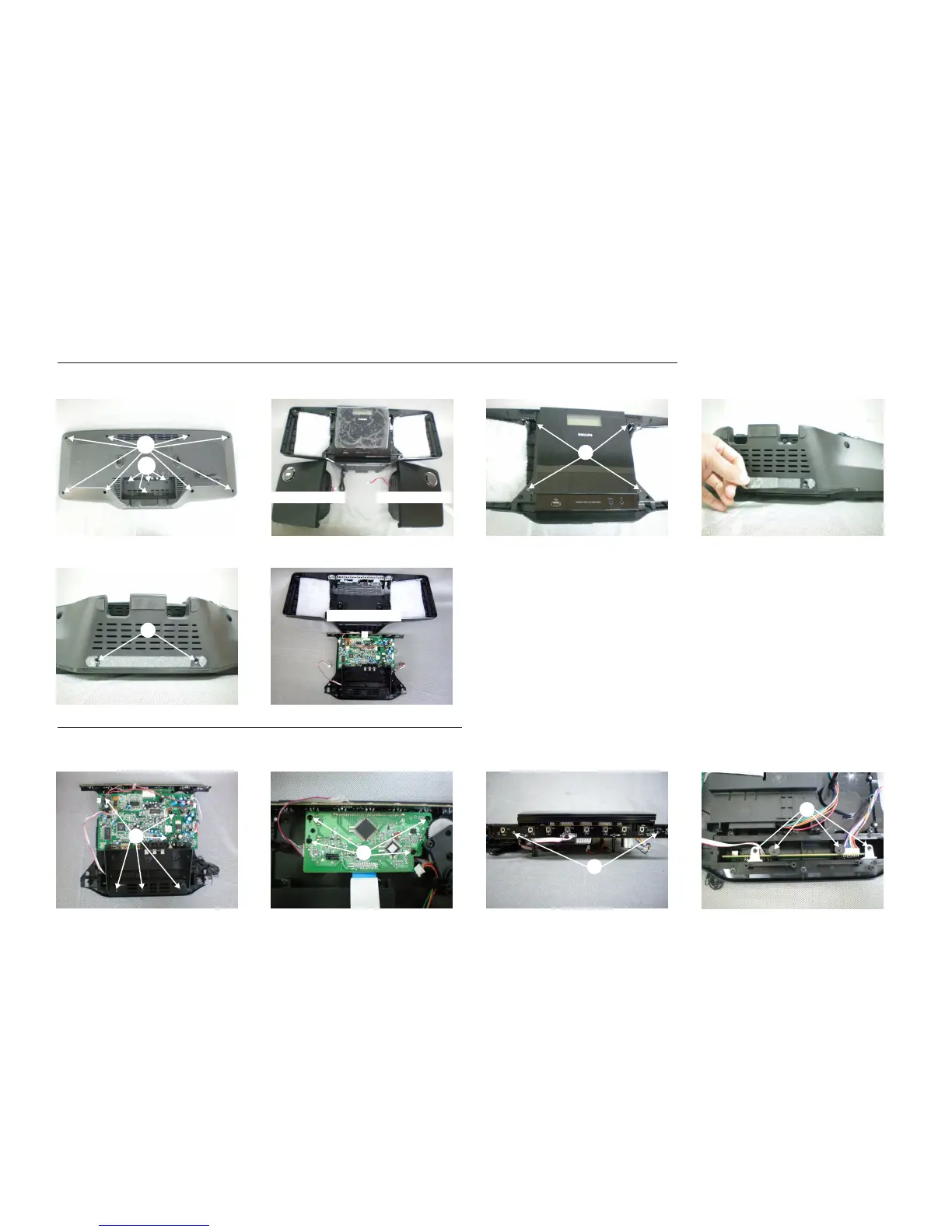
DISASSEMBLY DIAGRAM
Dismantling of the Rear Cabinet
Dismantling of the PCB Board
1)Remove 6 screws E as indicated to loosen the Main Board.
3)Remove 2 screws G as indicated to loosen the Key Board.
2)Remove 4 screws F as indicated to loosen the Display Board.
4)Remove 4 screws H as indicated to loosen the USB jack Board.
3)Remove a rubber foot at bottom of the unit as indicated.
2)Remove 4 screws B and 4 screws C as indicated.
4)Remove 2 screws D as indicated to loosen the Rear Cabinet.
1)Remove 8 screws A as indicated to loosen the speaker cabinet.
RIGHT SPEAKER CAB.
LEFT SPEAKER CAB.
B
A
C
D
D
E
F
G
H
REAR CABINET