EasyManua.ls Logo

Philips MCD280 - User Manual

Philips MCD280
31 pages
Print Icon
To Next Page IconTo Next Page
Loading...
version 1.0
MCD280
© 3141 785 30090
Service Manual
DVD Micro System
all versions
Published by SL 0439 Service Audio Printed in The Netherlands Subject to modification
©
Copyright 2004 Philips Consumer Electronics B.V. Eindhoven, The Netherlands
All rights reserved. No part of this publication may be reproduced, stored in a retrieval
system or transmitted, in any form or by any means, electronic, mechanical, photocopying,
or otherwise without the prior permission of Philips.
Handling chip components ............................................................1-1
Technical specification...................................................................2-1
Service tools..................................................................................2-1
Service measurement setup..........................................................2-2
Connections and controls......................................................3-1...3-4
Pin-description of ICs.....................................................................3-5
Disassembly diagram ....................................................................4-1
Set block diagram..........................................................................5-1
Set wiring diagram.........................................................................5-2
DISPLAY BOARD
circuit diagram ..........................................................................6-1
layout diagram ..........................................................................6-2
KEY BOARD & POWER BOARD & MICPHONE BOARD
circuit diagram ..........................................................................7-1
layout diagram ..........................................................................7-1
MPEG BOARD
circuit diagram ..................................................................8-1...8-4
layout diagram..................................................................8-5...8-6
TAPE BOARD
circuit diagram ..........................................................................9-1
layout diagram ..........................................................................9-2
COMBI BOARD
circuit diagram. .............................................................10-1...10-2
layout diagram..............................................................10-3...10-4
Exploded view diagram .....................................................11-1...11-2
Mechanical partslist.....................................................................11-2
Electrical partslist...............................................................12-1...12-2
TABLE OF CONTENTS
CLASS 1
LASER PRODUCT
Question and Answer IconNeed help?

Do you have a question about the Philips MCD280 and is the answer not in the manual?

Philips MCD280 Specifications

General IconGeneral
TypeMicro Hi-Fi System
Audio PlaybackMP3, WMA
RDSYes
CD PlayerYes
DVD PlayerYes
Karaoke FunctionNo
Remote ControlYes
Disc PlaybackCD, CD-R/RW, DVD
TunerFM
ConnectivityUSB, Aux-in
Speaker Type2-way bass reflex
Playback ModesRepeat, Program
USB Direct RecordingYes
Sound EnhancementDigital Sound Control, Dynamic Bass Boost

Summary

Handling Chip Components

Handling, Dismounting, and Mounting Procedures

Guidance on safely handling, dismounting, and mounting chip components.

ESD and General Safety Precautions

Important safety warnings and precautions for handling electronic components.

Correct Procedure Examples

Illustrations showing correct methods for component handling and soldering.

Technical Specifications

General and Amplifier Specifications

Technical details for the system's general operation and amplifier section.

Tuner and Cassette Recorder Specifications

Specifications for the FM/AM tuners and the audio cassette recorder.

CD, Video, and Service Information

Specifications for CD playback, video output, service tools, and ESD equipment.

Service Measurement Procedures

Tuner SW, AM, and CD Measurement

Procedures for measuring performance of Tuner SW, AM, and CD sections.

Connection and Controls

Remote and Unit Controls

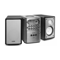
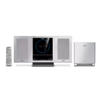
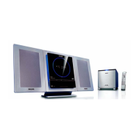
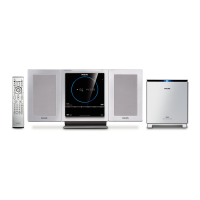
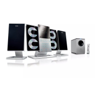
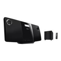
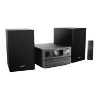
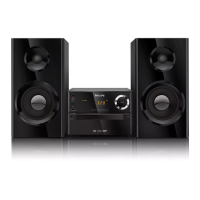
Layouts of remote control and main unit buttons and controls.

System Connection Procedures

Step-by-step instructions for connecting speakers, antennas, TV, and power.

Disassembly Diagram

Component Removal Steps

Diagram illustrating the order of disassembly and removal of system components.

Set Block Diagram

Set Wiring Diagram

Display Board Circuit Diagram

Display Board Layout Diagram

Schematic and physical layout of the display board circuitry.

Key Board Circuit Diagram

Key Board Layout Diagram

Schematic and layout for the system's key input board.

Power Board Circuit Diagram

Power Board Layout Diagram

Schematic and layout for the system's power supply board.

Microphone Board Circuit Diagram

Microphone Board Layout Diagram

Schematic and layout for the system's microphone input board.

MPEG Board Circuit Diagram

MPEG Board Layout Diagrams

Circuit schematics and physical layouts for the MPEG processing board.

Tape Board Circuit Diagram

Tape Board Layout Diagram

Schematic and physical layout of the tape deck control board.

Combi Board Circuit Diagram

Combi Board Layout Diagrams

Circuit schematics and physical layouts for the combined audio/radio board.

Exploded View Diagram

Component Identification

Diagram showing exploded view and identification of system parts.

Mechanical Parts List

Electrical Parts List

Miscellaneous Electrical Components

List of miscellaneous electrical parts, including fuses, jacks, and ICs.

Related product manuals