Interconnectivity Page 10 of 22
Firmware Programming Guide for PDIUSBD12
Philips Semiconductors - Asia Product Innovation Centre
Visit http://www.flexiusb.com
5.2 Control Endpoint Handler
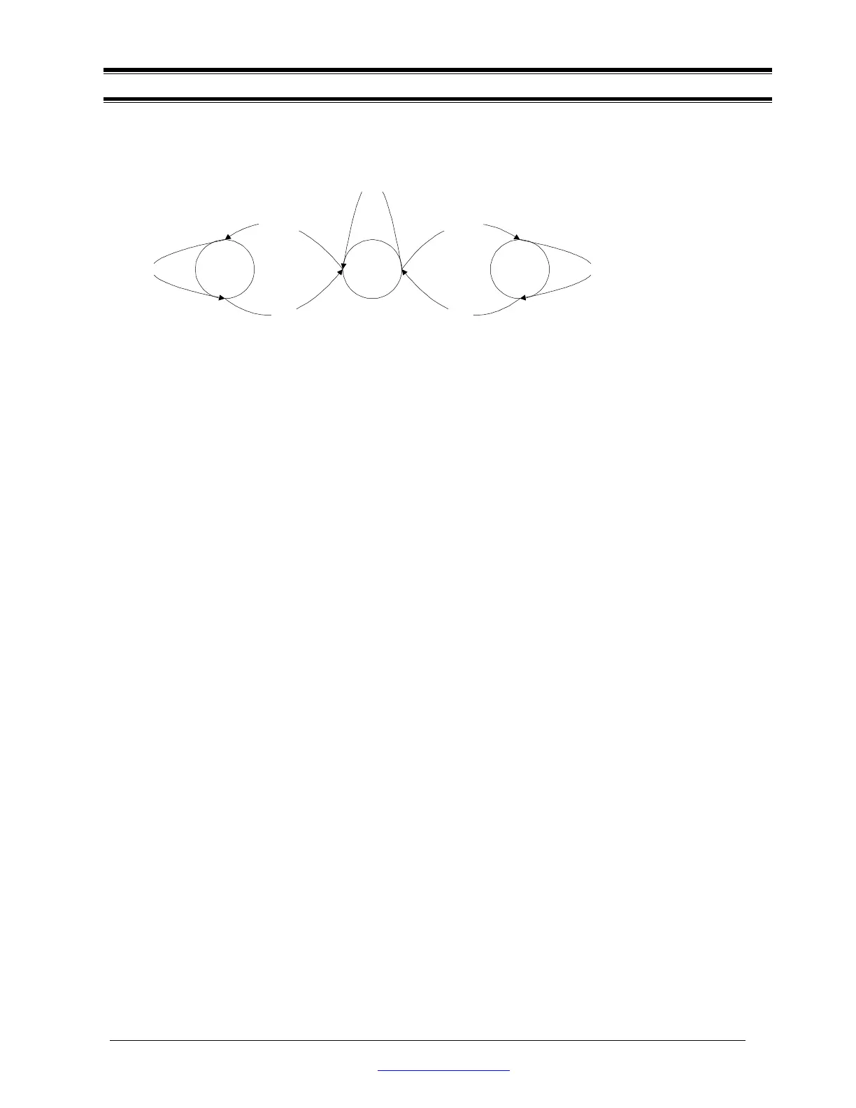
Control transfer always begins with the SETUP stage and then followed later by an optional DATA stage. It
then ends with the STATUS stage. The diagram below shows the various states of transitions on the Control
endpoints. The firmware uses these 3 states to handle Control transfer correctly.
IDLETRANSMIT RECEIVE
No-data Control
return Status
Control Write
Status
Control Read
Status
INs OUTs