Interconnectivity Page 5 of 22
Firmware Programming Guide for PDIUSBD12
Philips Semiconductors - Asia Product Innovation Centre
Visit http://www.flexiusb.com
2. Architecture
2.1 Firmware Structure
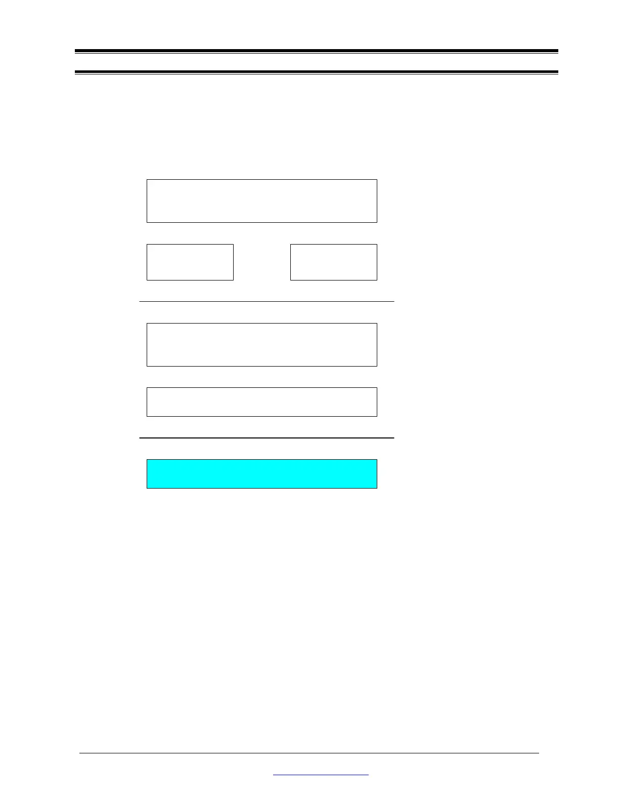
The firmware for the evaluation board consists of 6 building blocks. They are as follows:
2.1.1 Hardware Abstraction Layer - EPPHAL.C
This is the lowest layer code in the firmware, which performs hardware dependent I/O access to PDIUSBD12,
as well as Evaluation Board hardware. When porting the firmware to other CPU platforms, this part of code
always needs modifications or additions.
2.1.2 PDIUSBD12 Command Interface - D12CI.C
To further simplify programming with PDIUSBD12, the firmware defines a set of command interfaces, which
encapsulate all the functions used to access PDIUSBD12.
2.1.3 Interrupt Service Routine - ISR.C
This part of the code handles interrupt generated by PDIUSBD12. It retrieves data from PDIUSBD12's internal
FIFO to CPU memory, and set up proper event flags to inform Main Loop program for processing.
Hardware Abstraction Layer
EPPHAL.C
PDIUSBD12 Command Interface
D12CI.C
Main Loop: Dispatch USB Request, Read Test Keys, Control
LED, Process USB Bus Event, etc.
MAINLOOP.C
Interrupt Service Routine
ISR.C
Standard Request
CHAP_9.C
Vendor Request
PROTODMA.C