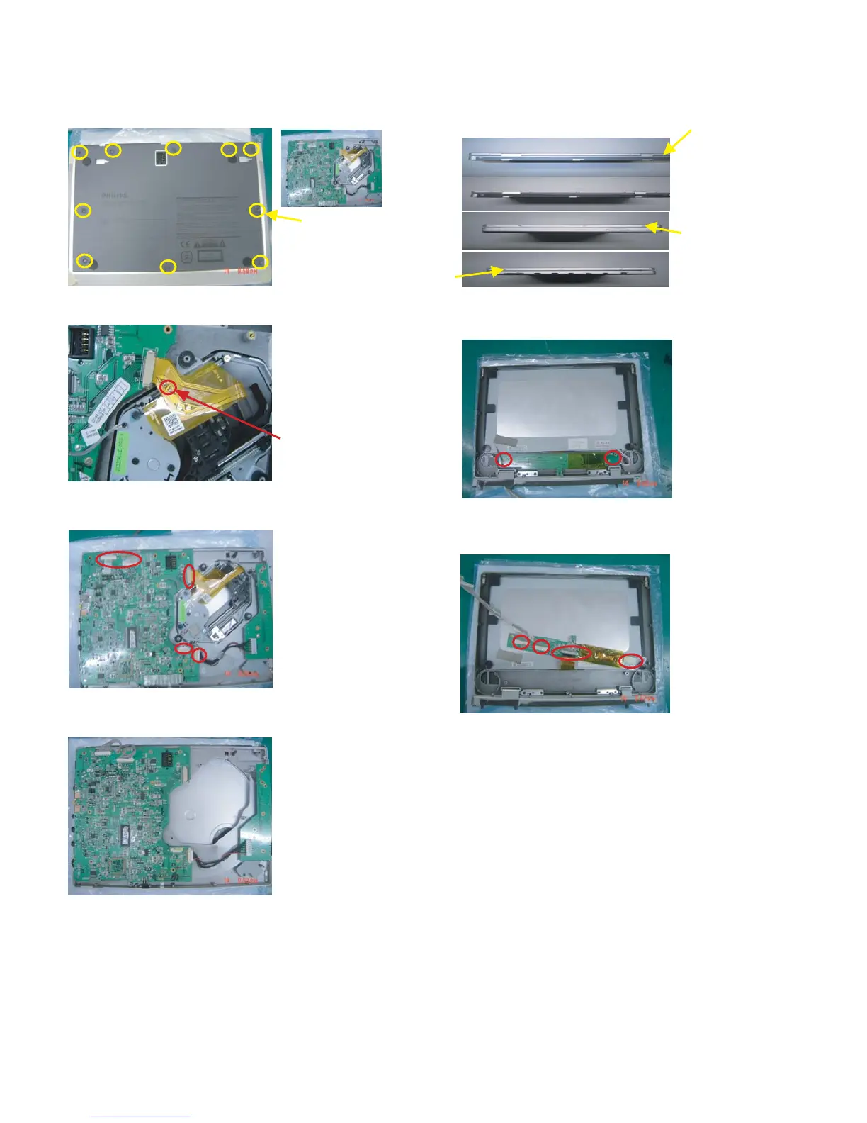
4.0 Mechnical instructions
Fig.1
screws
soldered
1. Back View as Fig.1
Remove screws to disassemble the base
2. Soldered short pattern for laser diode as Fig.2
3.
Fig.2
Disassemble the DVD drive and main board as Fig.3,4
Disconnect the DVD drive and main board
Fig.3
Take out the key board and other parts
5. Remove top cover as Fig.5
Fig.4
Fig.5
6. Disassemble the HV board as Fig.6
7.
Fig.6
Detach the LCD TFT as Fig.7
Remove screw to detach the LCD TFT
Fig.7
remove
screws
remove
screws
remove
screws