117
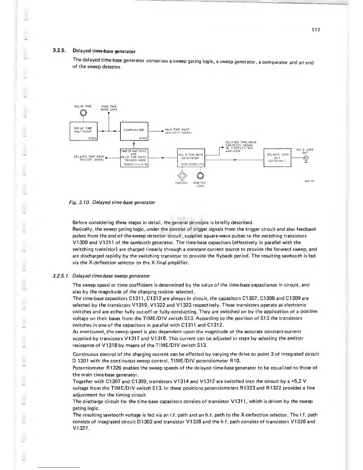
3.2.5.
Delayed
time-base
generator
The
delayed
time-base
generator
comprises
a sweep
gating
logic,
a sweep
generator,
a
comparator
and
an end
of
the
sweep
detector.
DELAY TIME MAIN TIME
0
IIMEvniV TIME/mV
CONI
Fig.
3.10.
Delayed
time-base generator
Before considering these stages in detail, the general principle is
briefly described.
Basically,
the sweep gating logic,
under the
control of trigger signals
from
the trigger circuit and also feedback
pulses from the
end-of-the-sweep detector circuit, supplies square-wave pulses to the switching transistors
VI
309 and VI 31 1
of
the sawtooth generator. The
time-base capacitors (effectively
in
parallel
with
the
switching transistor)
are
charged linearly through
a
constant-current
source
to
provide
the forward sweep, and
are discharged rapidly by the switching transistor to
provide
the
flyback period. The resulting sawtooth
is
fed
via the X-deflection selector
to the
X-final amplifier.
3.2.5.
1.
Delayed time-base sweep generator
The sweep
speed or time
coefficient
is
determined
by
the value of
the time-base capacitance in circuit, and
also by the magnitude of the charging resistor selected.
The time-base capacitors Cl 31
1,
Cl 312 are always in circuit,
the capacitors
Cl
307,
Cl 308
and Cl 309 are
selected
by the transistors
VI
31
9,
VI 322 and VI 323
respectively.
These transistors
operate as
electronic
switches
and
are
either fully cut-off
or
fully-conducting.
They
are
switched on by the application of a
positive
voltage on their
bases from the
TIME/DIV switch SI 3.
According to the position of SI 3 the transistors
switches in one
of
the capacitors in parallel with Cl 31
1
and Cl
31
2.
As mentioned,
the
sweep speed
is also
dependent upon the magnitude of the accurate constant-current
supplied by transistors VI 31
7
and VI 31
8.
This current can be
adjusted in steps by selecting the
emitter
resistance
of VI
318 by
means of
the
TIME/DIV switch SI 3.
Continuous control of the charging current can be
effected
by
varying the
drive
to
point
3
of integrated circuit
D
1301
with
the continuous sweep control,
TIME/DIV
potentiometer
RIO.
Potentiometer
R1326 enables the sweep speeds of the delayed
time-base generator to be equalized to
those of
the main
time-base generator.
Together with
Cl 307 and Cl
309,
transistors
VI 31
4
and VI
31
2 are
switched into the circuit by a
^5,2
V
voltage from
the
TIME/DIV
switch S13.
In
these
positions
potentiometers R1323 and R1322 provides a
fine
adjustment for
the
timing circuit.
The discharge
circuit for
the time-base capacitors consists of
transistor VI 31
1 ,
which is driven by the
sweep
gating logic.
The
resulting sawtooth voltage is fed via an l.f. path and an h.f. path to the
X-deflection selector. The l.f. path
consists of
integrated circuit D1 302 and transistor
VI
328 and
the h.f. path consists of transistors VI 326 and
V1327.
 Loading...

