14
Gaining access
to
parts
A.
THE
BATTERIES
•
- Remove
the
two screws
at
the rear.
The
rear panel then
can
be removed.
- Remove the connection wires from the battery.
- Remove the
battery
damp.
- Remove the batteries.
-
Fit
the new batteries in the
appar
atu
s.
- Refit the
battery
d amp.
-
Connect
the series-connection wire to the new batterie
s.
-
Connect
the two remaining connection wires to the new batteries.
(The batteries are provided with two different termina
ls
for the positive
and
negative poles, so
that
it
is
impossible to interchange the connec-
tions.)
- Refit
the
rear panel.
B.
THE
PRINTED
WIRING
BOARD
Remove the rear
panel
(see V-A).
The
cabinet
then
can
be removed.
The
printed wiring
board
(with all
component
s)
is
then acce
ss
ible.
Tt
is
provided
with figures l ... 8,
corresponding
to figures 1 ... 8 in the circuit
diagram. These figures indicate the connection points between the
part
s
mounted
on
the
cha
ss
is
and
the printed wiring
board
.
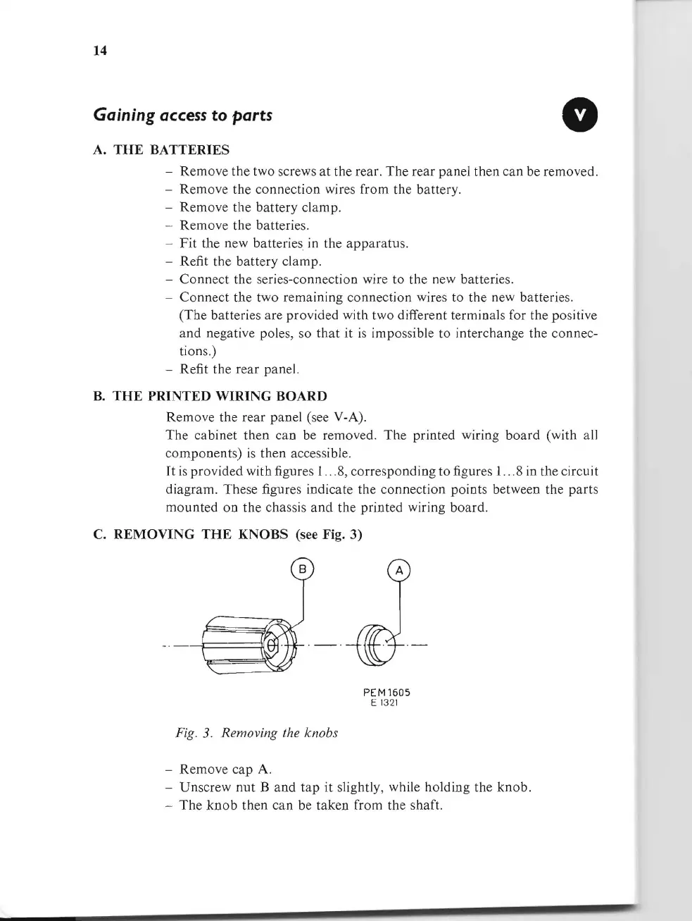
C.
REMOVING
THE
KNOBS (see Fig. 3)
PEM1605
E 1
32
1
Fig.
3.
Removing the knobs
- Remove
cap
A.
- Unscrew
nut
B
and
tap
it
slightly, while holding the
knob.
-
The
knob
then
can
be taken from the shaft.