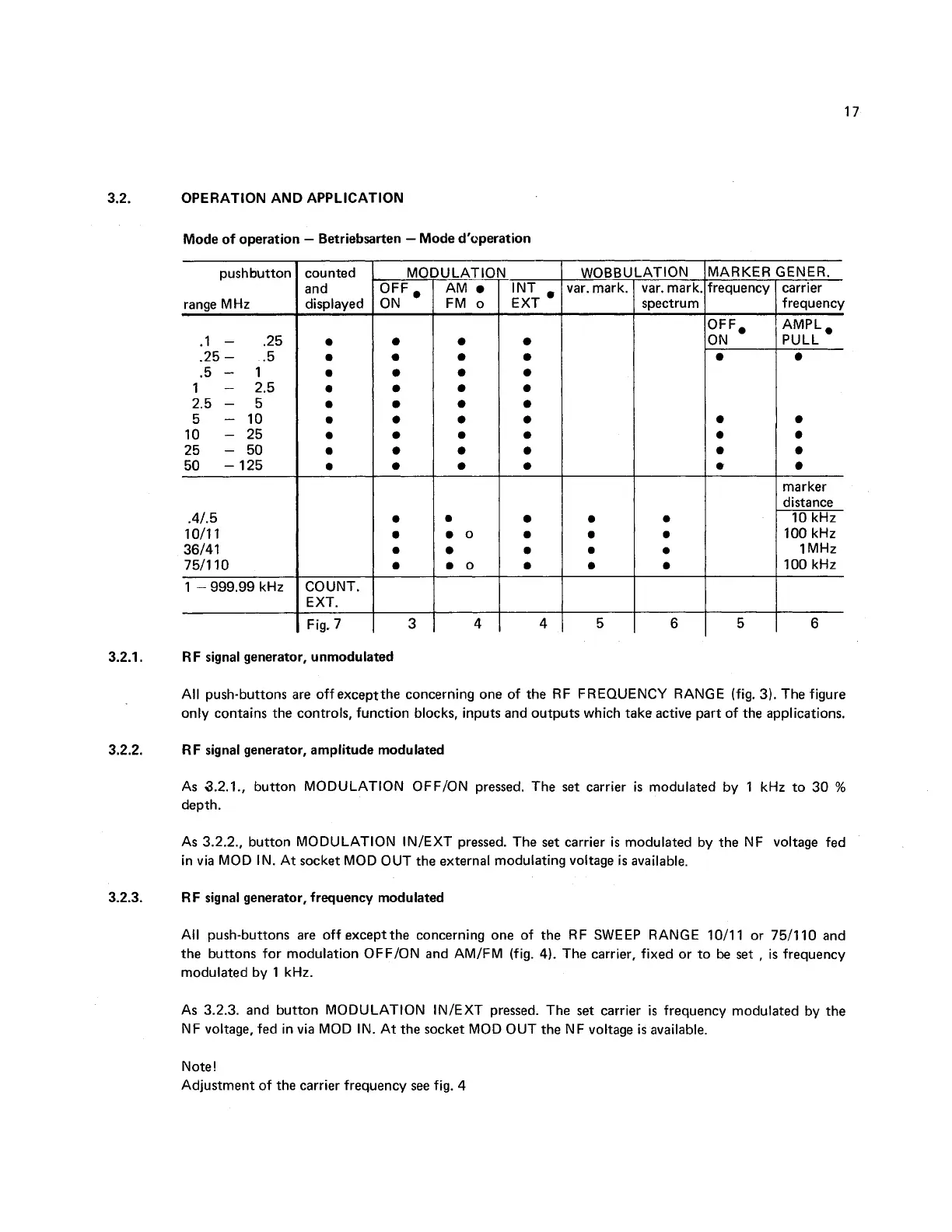
OPERATION AND APPLICATION
Mode of operation
-
Betriebsarten
-
Mode d'operation
Fig. 7
+
M
C
OFF
,
0
N
0
ULATIC
AM
FM o
--
INT
.
E XT
WOBBULATION
AARKER
requency
IFF,
I
N
e
iENER.
carrier
frequency
AMPL,
PULL
marker
distance
10 kHz
100 kHz
1
MHz
100 kHz
RF signal generator, unmodulated
All push-buttons are off
exceptthe concerning one of the RF FREQUENCY RANGE (fig. 3). The figure
only contains the controls, function blocks, inputs and outputs which take active part of the applications.
RF signal generator, amplitude modulated
As 3.2.1., button MODULATION OFFION pressed. The set carrier
is
modulated by 1 kHz to 30
%
depth.
As 3.2.2.. button MODULATION INIEXT pressed. The set carrier
is
modulated by the NF voltage fed
in via MOD IN. At socket MOD OUT the external modulating voltage
is
available.
RF signal generator, frequency modulated
All push-buttons are off except the concerning one of the RF SWEEP RANGE 1011 1 or 7511 10 and
the buttons for modulation OFFION and AMIFM (fig.
4).
The carrier, fixed or to
be
set
,
is frequency
modulated by 1 kHz.
As 3.2.3. and button MODULATION INIEXT pressed. The set carrier
is
frequency modulated by the
NF voltage, fed in via MOD IN. At the socket MOD OUT the NF voltage
is
available.
Note!
Adjustment of the carrier frequency see fig.
4
 Loading...