4.2. ACCESS
TO
PARTS
Before dismantling the instrument, the safety regulations in accordance with para. 2.1. must be strictly
observed.
4.2.1. Cabinet,
see
2.4.
4.2.2. Knobs
-
Remove the cap from the knob.
-
Unscrew the nut and remove the knob.
-
When replacing the knob, ensure that the white mark
is
correctly aligned with the text plate markings.
4.2.3. Text plate
-
Remove the cabinet,
see
2.4.
-
Remove the
8
turn-knobs, see 4.2.2.
-
Remove the
3
bearing bushes.
-
Remove the plastic cover of the mains switch.
-
The text plate can now be removed.
4.2.4. Mains transformer
-
Unscrew the right-hand side frame of the case. The holding angle can remain connected to the side
frame.
4.2.5.
Unit
I,
variable capacitor
550:
are mounted in the upper part of the cast RF housing.
Unit 4, attenuator switch,attenuator potentiometer: are mounted in the bottom part of the cast RF housing.
4.2.6. Pushbutton unit
Replacing a pushbutton lever.
The single pushbutton lever can be replaced from the front.
-
Push the spring towards the pushbuttons.
-
Remove the wire strap or plastic part.
-
Carefully tear the pushbutton lever out of the pushbutton.
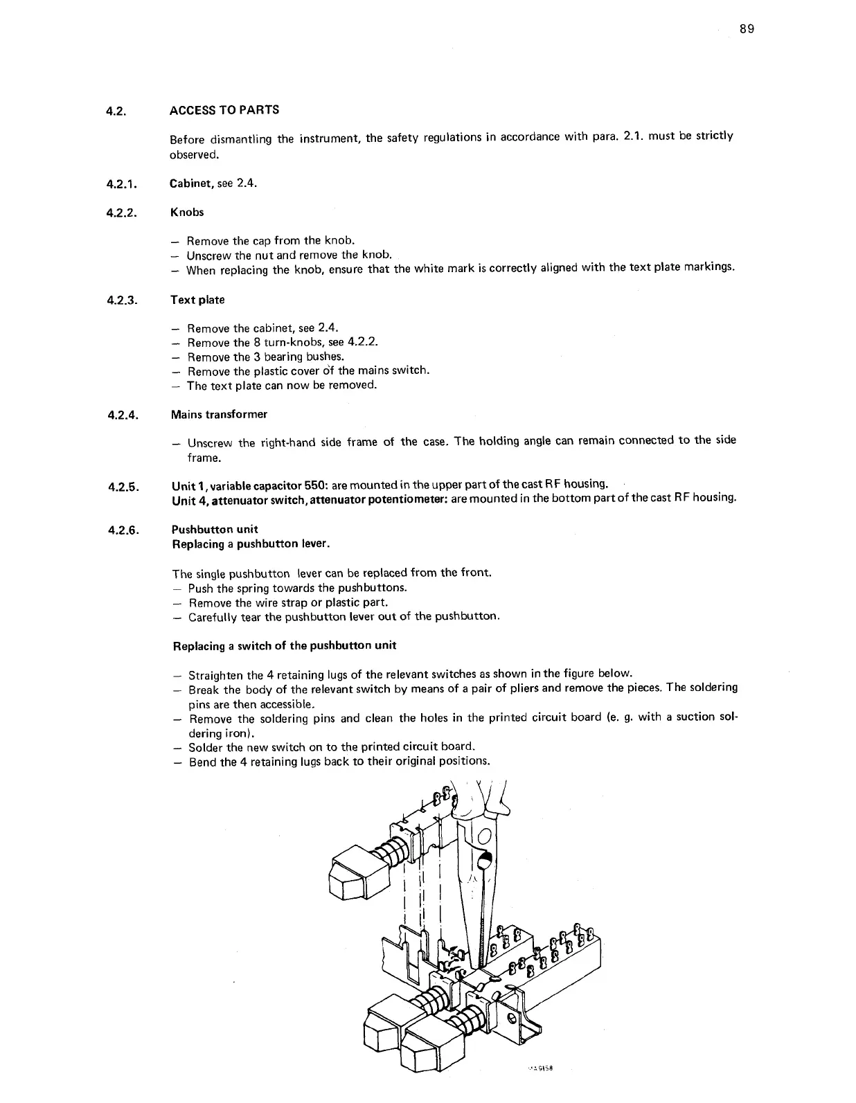
Replacing a switch of the pushbutton unit
-
Straighten the 4 retaining lugs of the relevant switches as shown in the figure below.
-
Break the body of the relevant switch by means of a pair of pliers and remove the pieces. The soldering
pins are then accessible.
-
Remove the soldering pins and clean the holes in the printed circuit board (e. g. with a suction sol-
dering iron).
-
Solder the new switch on to the printed circuit board.
-
Bend the
4
retaining lugs back to their original positions.