Philips Lighting North America Corporation
200 Franklin Square Drive
Somerset, NJ 08873, USA
Phone: 855-486-2216
www.philips.com/luminaires
Philips Lighting Canada Ltd.
281 Hillmount Road,
Markham ON, Canada L6C 2S3
Phone: 800-668-9008
www.philips.com/luminaires
GENERAL INSTRUCTIONS
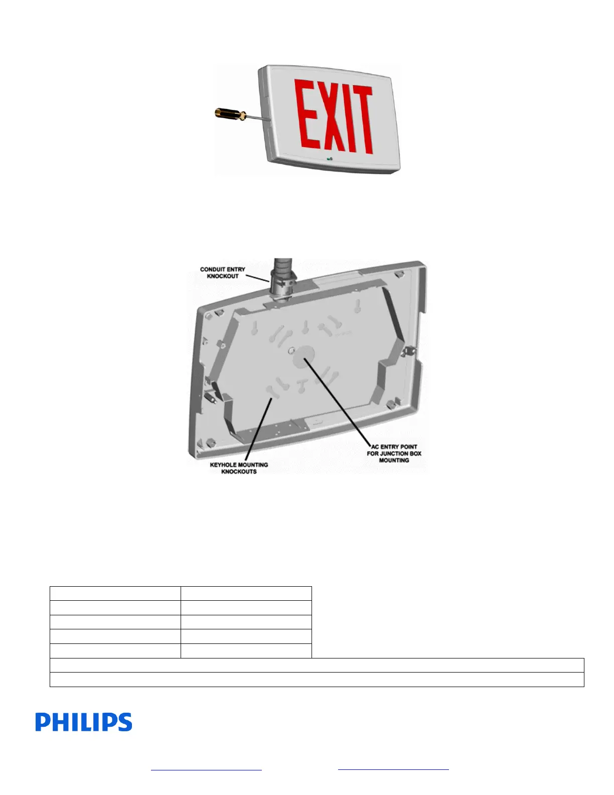
STEP 1 –
Prepare the exit for installation by removing the backplate. Prying points are provided around the
perimeter of the housing to allow the use of a screwdriver as shown. Remove desired directional
indicators from stencil by rolling back the colored lens and using a punch and hammer to knockout them
out from the inside of the stencil. Determine desired mounting style and proceed to the appropriate
“STEP 2”.
STEP 2 for Wall Mounting –
Remove keyhole knockouts for securing the backplate to the mounting surface as necessary. Keyhole
knockout patterns are provided for 3-1/2” and 4” octagonal boxes, single gang boxes and widely spaced
keyhole knockouts are provided for use with wall anchors (not provided). A large central knockout is
provided for AC service entry or the conduit entry knockout in the upper surface of the backplate may
be removed (use ½” flex conduit). A four pole connector assembly is provided on the stencil/electronics
assembly for AC service connection. Make AC service connections according to the table below. Snap
stencil/electronics assembly to backplate and refer to operating instructions section.
CAUTION: Unused primary wire must be capped off!