Do you have a question about the Philips SM30 and is the answer not in the manual?
Describes the central unit housing the microprocessor and plug-in modules for system control.
Explains how the system's functions are programmed via the front panel display and keys.
Details the various plug-in modules that expand the SM30 system's capabilities.
Describes the primary input device for routing calls and announcements.
Explains the built-in generator for attention tones and alarm signals.
Details the connection and playback of background music sources.
Information on connecting an emergency power supply for system reliability.
Illustrates the system's architecture and interconnections between components.
Describes a step-by-step sequence of a typical announcement or paging call.
Explains how generating a call can activate external equipment via relays.
Details how relays ensure announcements play at full volume, overriding settings.
Explains making calls using pre-programmed function keys for efficiency.
Describes activating calls via microphone or remote switches.
Explains the programmable delay before system activation to conserve power.
Describes how higher priority calls can interrupt alarm signals.
Details the alpha-numeric LCD display, LEDs, and programming keys.
Describes the essential Line Output and Power Supply modules.
Overview of Control Centre delivery and module slot configuration.
Instructions for safely accessing the Control Centre's internal components.
Procedure for configuring the unit to the correct mains voltage supply.
Information on connecting an external DC supply for backup power.
Guidance on connecting an earth wire for interference reduction or backup.
Procedures and considerations for rack mounting the SM30 Control Centre.
Steps for connecting amplifiers for two-channel and one-channel systems.
Details on the electret microphone, compressor, and line output capabilities.
Explains keypad, function keys, LEDs, and redial for call station operation.
Covers mounting the zone template and connecting the call station.
Guides on setting microphone gain and LED intensity.
Instructions for making calls via keypad and function keys.
Covers module mounting in the control centre and call station connections.
Explains volume level controls for signal source alignment.
Details remote switching, line input, and bass cut facilities for microphones.
Covers module mounting and connecting microphones.
Explains control input functions, remote music control, and audio distribution.
Covers module mounting and wiring control inputs.
Details programming options for normal call activation and remote control.
Covers module mounting and microphone input for recording.
Explains output volume control for recorded messages.
Guides on clearing memory, recording, and overwriting messages.
Covers module mounting and connecting music sources.
Explains individual input volume and tone controls.
How control centre keys manage music volume and source selection.
Details software routing and display status for music sources.
Covers module mounting and terminations for amplifier connections.
Explains linking modules for expanded zone coverage.
Discusses system setups with multiple amplifiers for zone distribution.
Details relay functions, power-on delay, and external audio source activation.
Describes the functions and programming of relays 3 through 12.
Explains how relays control loudspeaker volume overrides.
Covers module mounting and wiring control relays.
Details programming options for relays, including power-on delay and zone coupling.
Provides a concise overview of user programming steps and selections.
Explains the programming process, modes, and navigation.
Guides on programming Call Stations, Microphones, Control Inputs, and Music Routing.
Allows selection of zones for music playback and routing.
Outlines installer programming steps for system setup and configuration.
Covers system down, installer mode, language, and hardware storage.
Details advanced configuration options for the system.
Specifies hardware, message module, and audio output characteristics.
Details audio switching and power on/off mute suppression levels.
Specifies pilot tone volume and mute characteristics.
Lists AC and DC switching capabilities for CRM output relays.
Covers voltage settings, frequency, power consumption, and fuses.
Details DC voltage requirements and protection for emergency power.
Provides dimensions and weight for rack and desktop use.
Specifies operating and storage conditions for ambient temperature and humidity.
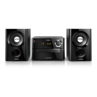
| Brand | Philips |
|---|---|
| Model | SM30 |
| Output Power | 2 x 15W |
| Loudspeaker type | 2-way |
| Bass reflex | Yes |
| Tuner Bands | FM |
| Playback Media | CD |
| Inputs | AUX |
| Outputs | Headphone |

