4-2
On
the
display
appears
"3".
(Dependent
on
the
length
of
the
lead-in track music will
be
reproduced after
approx.
1 min.).
In
this
state
it
is
possible
to
move
the arm
by
means
of
the
SEARCH FORW and
the
SEARCH REV keys
to
the
outside
and
to
the
inside resp.
Now
the
motion
is
controlled
by
the
µP
and the arm moves
by
steps
of
'
64
tracks
as long
as
the
key
is depressed.
If
the
laser
is
disturbed in position "3" (as a result
of
braking
or
removal
of
the
disk)
the
player will
jump
back
to
position
"O".
This
also holds
good
if
position
"1
• and "2"
Is
disturbed and position "3"
is
called.
The
servicing programme can
be
left
by
switching
the
mains switch (POWER ON/OFF)
off
and
on
(hardware
reset).
Specification measurement
l
CD
PLAYER
-----;
FILTER
R
Fig. 4
~NANO
DISTORTION
METER
o.g.
SOVNO
TECMNOLDGY
ST
17008
30
,sg
All
To
measure
the
specification use can be made
of
audio
test
disc
4822
397
30095.
Use
13th
order
filter 4822 395 30204
to
measure (see
Fig.4):
-
Total
harmonic distortion (THD)
- Intermodulation distortion
- Signal-to-noise ratio (S/N)
Continuous burning
of
the
laser
- Bridge
c!!Q_acitor
2583
on
the
decoding panel.
- Connect
Si
(=
pin
20
of
6525
on
the servo + preampi.
panel)
to
ground.
- Switch
on
the
supply
voltage.
-
Now
the
laser will burn continuously.
Note: Danger
Invisible
laser
radiation.
Avoid direct
exposure
to
beam.
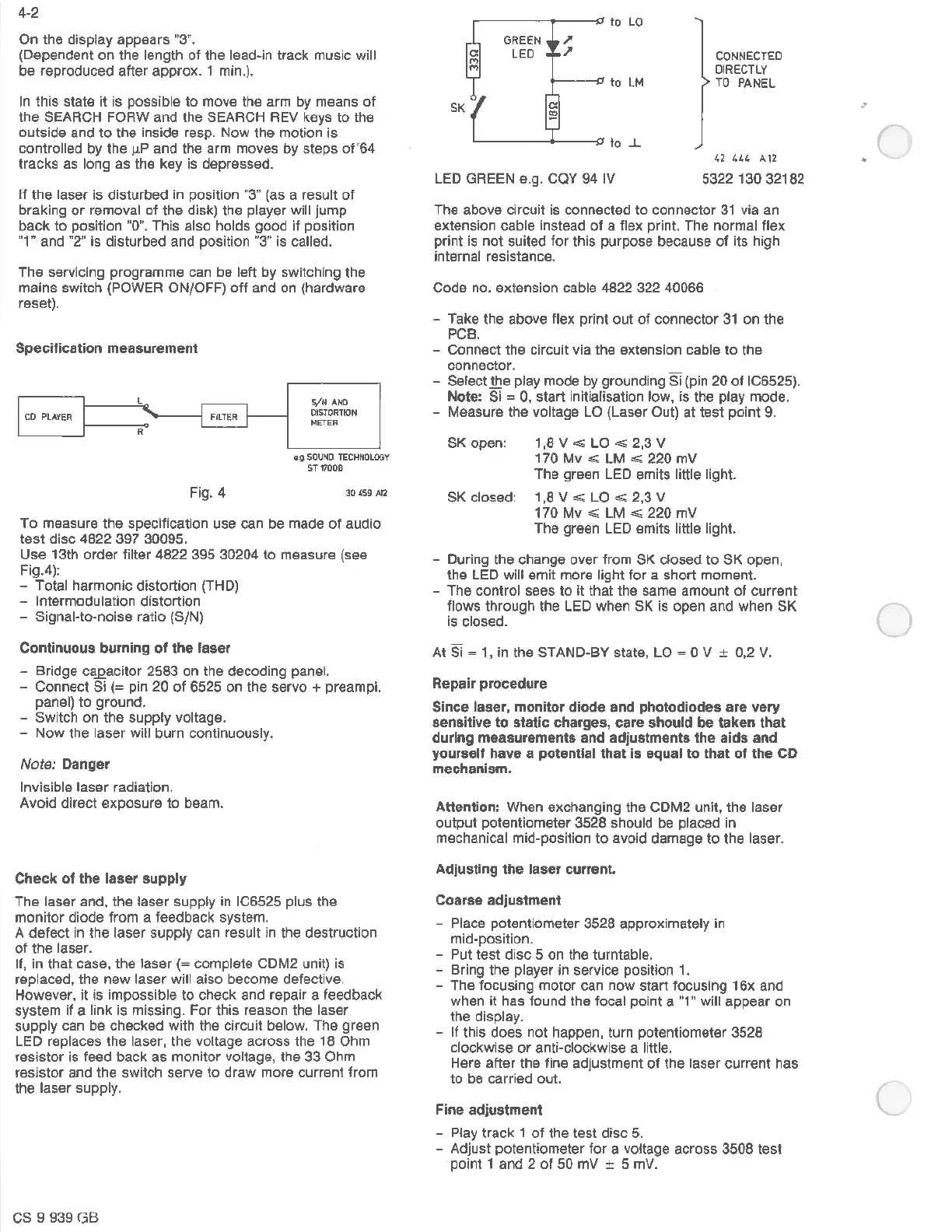
Check
of
the
laser
supply
The
laser and, the laser supply in IC6525 plus
the
monitor
diode
from
a feedback system.
A
defect
in
the
laser
supply
can result in the destruction
of
the
laser.
If,
in
that
case,
the
laser
(=
complete CDM2 unit) is
replaced, the
new
laser will also become defective.
However,
it
is
impossible
to
check
and repair a feedback
system if a link is missing.
For
this
reason
the
laser
supply
can be checked with
the
circuit below.
The
green
LED replaces
the
laser,
the
voltage across
the
18
Ohm
resistor
is feed
back
as
monitor
voltage, the 33 Ohm
resistor
and
the
switch serve
to
draw
more current from
the laser supply.
CS 9 939
GB
~---------,...
to
LO
LED GREEN e.g. CQY
94
IV
CONNECTED
DIRECTLY
TO
PANEL
42
444
A12
5322 130 32182
The above circuit is connected
to
connector
31
via an
extension cable instead
of
a flex print. The normal flex
print
is
not
suited
for
this
purpose because
of
its high
internal resistance.
Code
no. extension cable 4822 322 40066
- Take
the
above flex print
out
of
connector
31
on
the
PCB.
- Connect
the
circuit
via
the
extension cable
to
the
connector.
- Select
the
play mode by grounding Si (pin
20
of
IC6525).
Note:
Si=
0,
start
initialisation
low,
is
the play mode.
- Measure
the
voltage LO (Laser Out) at
test
point
9.
SK open: 1,8
V,,;;;
LO,,;;;
2,3
V
170
Mv
.,,,:;
LM
.,,,:;
220
mV
The
green LED emits little light.
SK
closed: 1
,8
V
.,,,:;
LO
.,,,:;
2,3 V
170
Mv
,,;;;
LM
,,;;;
220
mV
The
green LED emits little light.
- During
the
change
over
from SK closed
to
SK
open,
the
LED will
emit
more light
for
a
short
moment.
-
The
control sees
to
It
that
the same amount
of
current
flows
through
the
LED
when
SK is open and
when
SK
is closed.
At
si = 1, in
the
STAND-BY state,
LO=
0 V ± 0,2 V.
Repair procedure
Since
laser, monitor diode and photodiodes
are
very
sensitive to static charges,
care
should
be
taken
that
during measurements and adjustments
the
aids
and
yourself
have
a potentlal
that
Is equal to
that
of
the
CD
mechanism.
Attention:
When exchanging
the
CDM2 unit,
the
laser
output
potentiometer 3528 should be placed in
mechanical mid-position
to
avoid damage
to
the
laser.
Adjusting
the
laser
current
Coarse adjustment
- Place potentiometer 3528 approximately in
mid-position.
- Put
test
disc
5
on
the turntable.
- Bring
the
player in service position 1.
-
The
focusing
motor
can
now
start
focusing
16x
and
when
it
has found
the
focal point a "1" will appear
on
the
display.
-
If
this
does
not
happen, turn potentiometer 3528
clockwise
or
anti-clockwise a little.
Here
after
the
fine adjustment
of
the
laser
current
has
to
be carried out.
Fine
adjustment
- Play track 1
of
the
test
disc
5.
- Adjust potentiometer
for
a voltage across 3508
test
point 1
and
2
of
50
mV
± 5 mV.
(
0
(
 Loading...