'
C
0
(
uJ
□~
DtOffM
AUDIO
Adjustment of
the
focus off-set
Coarse adjustment
A.
- Place potentiometer 3517 approximately in
mid-position.
- Put
test
disc 5 on the turntable.
- Bring the player
in
service position 1.
- The focusing
motor
can now start focusing 16x and
when
it
has found the focal point a "1" will appear
on the display.
-
If
this does
not
happen, turn potentiometer 3517
clockwise
or
anti-clockwise a little.
- Here after the fine adjustment
of
the focus off-set
has to be carried out.
B. - Place with potentiometer 3517 the focusing motor
in optical horizontal position.
- Here after the fine adjustment
of
the focus off-set
has to be carried out.
Fine
adjustment
- Bring the player in service position
2.
- Adjust potentiometer 3517
for
a voltage across 2545
(test point
27)
of
400
mV
±
40
mv.
Note: Notice that the CDM
is
in
a horizontal position.
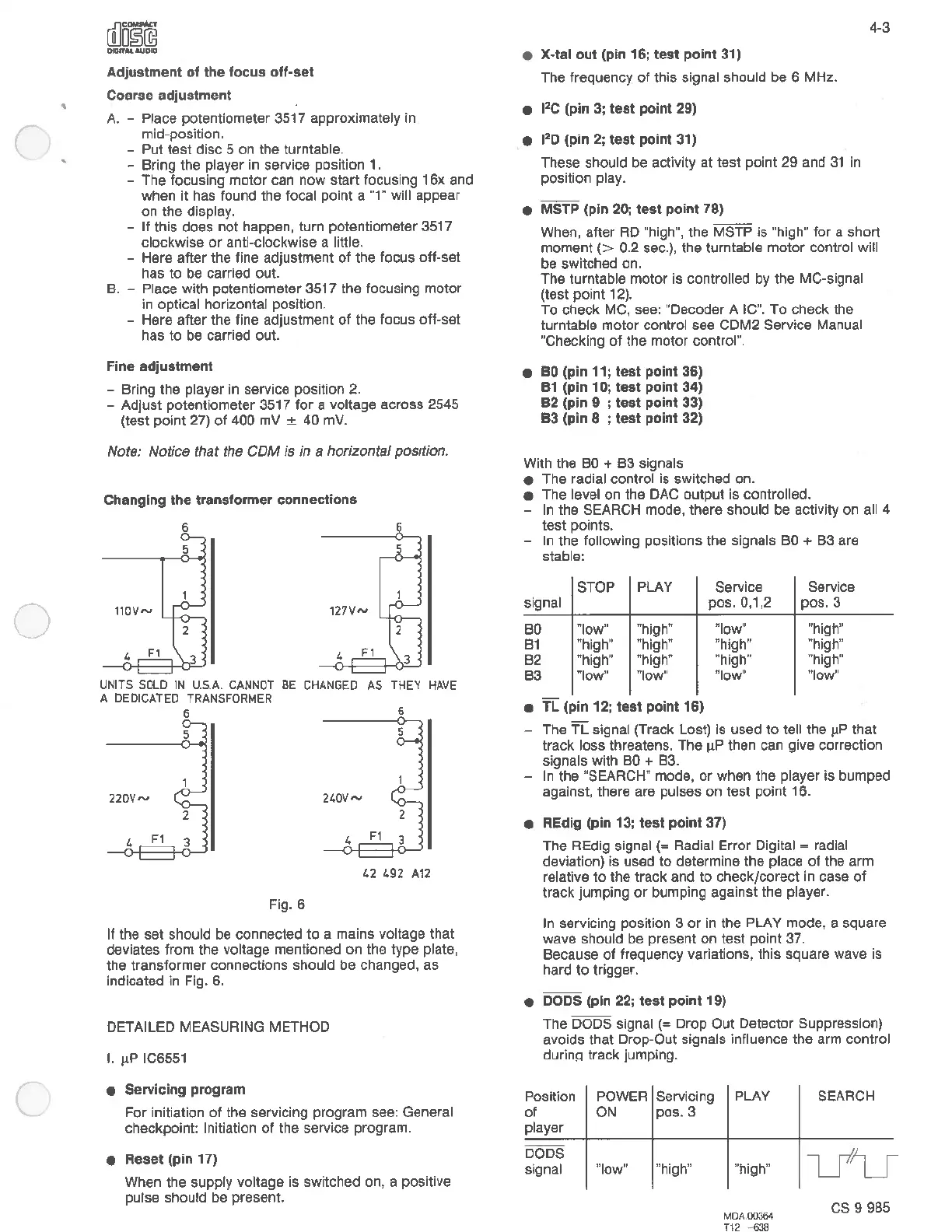
Changing
the
transformer connections
6
5
UNITS
SOLD
IN
U.S.A.
CANNOT BE CHANGED
A DEDICATED
TRANSFORMER
6
5
22DV~
240V~
Fig. 6
AS
THEY
HAVE
2
42
492
A12
If the set should be connected
to
a mains voltage that
deviates
from
the voltage mentioned on the type plate,
the transformer connections should
be
changed,
as
indicated in Fig.
6.
DETAILED MEASURING METHOD
I. µP IC6551
• Servicing program
For
initiation
of
the servicing program see: General
checkpoint: Initiation
of
the service program.
•
Reset
(pin
17)
When the supply voltage is switched on, a positive
pulse should be present.
• X•tal out (pin 16;
test
point 31)
The frequency
of
this signal should
be
6 MHz.
• 1
2
c (pin 3;
test
point
29)
• 1
2
0 (pin
2;
test
point
31)
These should be activity
at
test point
29
and
31
in
position play.
•
MSTP
(pin 20;
test
point
78)
4-3
When, after RD "high", the MSTP
is
"high"
for
a short
moment(>
0.2 sec.), the turntable
motor
control will
be
switched on.
The turntable motor is controlled by the MC-signal
(test point
12).
To check MC, see: "Decoder A IC".
To
check the
turntable motor control see CDM2 Service Manual
"Checking
of
the motor control".
•
BO
(pin 11;
test
point
36)
81
(pin 1
O;
test
point 34)
B2
(pin 9 ;
test
point
33)
B3
(pin 8 ;
test
point
32)
With the
BO
+
83
signals
• The radial control is switched on.
• The level on the
DAC
output is controlled.
- In the SEARCH mode, there should
be
activity on all 4
test
points.
In the following positions the signals
BO
+
83
are
stable:
STOP
PLAY
Service Service
signal
pas. 0,1,2
pos.3
BO
"low" "high"
"low" "high"
81 "high" "high" "high" "high"
82
"high" "high" "high"
"high"
83
"low"
"low" "low"
"low"
•
TL
(pin 12; test point
16)
- The
TL
signal (Track Lost) Is used
to
tell the µP that
track loss threatens. The µP then can give correction
signals with
BO
+ 83.
- In the "SEARCH" mode,
or
when the player
is
bumped
against, there are pulses on test point 16.
• REdig (pin 13;
test
point 37)
The REdig signal
(=
Radial Error Digital = radial
deviation)
is
used
to
determine the place
of
the arm
relative
to
the track and
to
check/corect in case
of
track jumping
or
bumping against the player.
In servicing position 3
or
in
the PLAY mode, a square
wave should be present on test point 37.
Because
of
frequency variations, this square wave is
hard
to
trigger.
• DODS (pin 22; test point
19)
The DODS signal
(=
Drop Out Detector Suppression)
avoids
that
Drop-Out signals influence
the
arm control
durinq track jumping.
Position POWER Servicing
PLAY
SEARCH
of
ON
pos.3
player
DODS
u'
U
signal
11
low"
"high" "high"
MDA00364
cs
9 985
T12
-638
 Loading...