Mechanical Instructions
EN 9Q529.1A LA 4.
4.3 Assy/Panel Removal VE8 Styling
Note: the following disassembly-instructions apply to the
European sets. Small deviations with the AP sets occur.
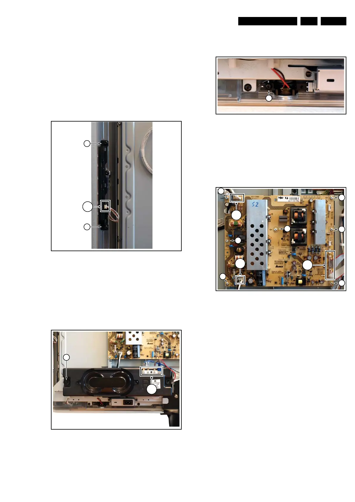
4.3.1 Key Board
Refer to next figure for details.
1. Unplug the key board connector [1] from the IR & LED
board.
2. Remove the screws [2].
3. Lift the unit and take it out of the set.
When defective, replace the whole unit.
Figure 4-3 Key Board
4.3.2 Bass-midrange Speakers
Refer to next figure for details.
1. Release the speaker connectors [1] from unit.
2. Remove the screw [1] and lift the whole unit from the set.
Take the speakers out together with their casing. When
defective, replace the whole unit.
Figure 4-4 Bass-midrange Speaker
4.3.3 Tweeters
Refer to next figure for details.
1. Remove the bass-midrange speaker as described earlier.
2. Remove the screw [1] and lift the whole unit from the set.
When defective, replace the whole unit.
Figure 4-5 Tweeters
4.3.4 Display Supply Panel
Refer to next figure for details.
1. Unplug the connectors [1].
2. Remove the fixation screws [2].
3. Take the board out.
Figure 4-6 Display Supply Panel
4.3.5 Small Signal Board (SSB)
Refer to next figure for details.
Caution: it is mandatory to remount all different screws at their
original position during re-assembly. Failure to do so may result
in damaging the SSB.
1. Unplug the LVDS connector(s) [1].
Caution: be careful, as this is a very fragile connector!
2. Unplug the connectors [2].
3. Remove the screw [3] from the side I/O cover.
4. Remove the fixation screws [4].
5. The SSB can now be taken out of the set.
I_17660_110.eps
130308
2
2
1
I_17660_111.eps
130308
1
2
I_17660_112.eps
130308
1
I_17660_113.eps
130308
1
2
2
2
2
2
2
2
1
2
(
2x
)