USER MANUAL – Arrow QG™/VI™
© 2022 Phillips Connect LLC Arrow QG/VI User Manual Page 3 of 10
2. DESIGN
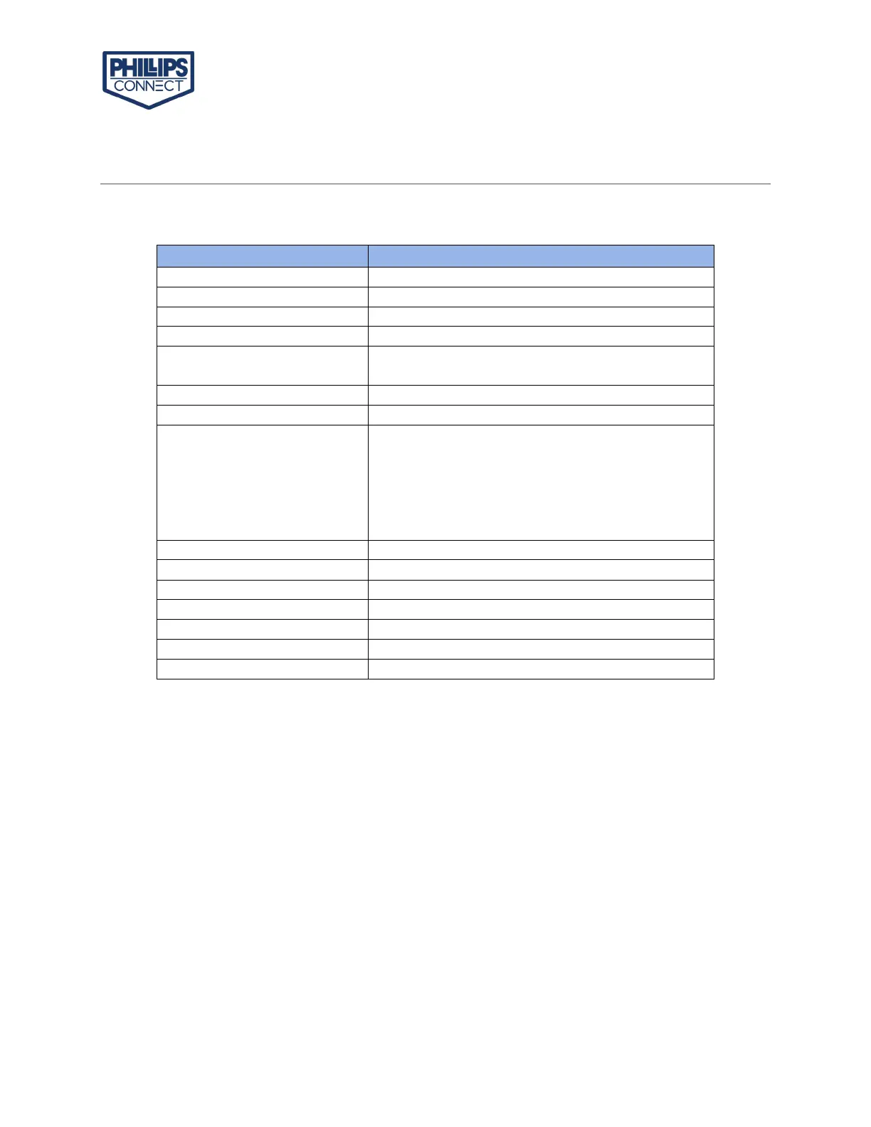
2.1 BASIC HARDWARE
4G band support Band 2/4/5/12/13/25/26
BLE 5.0: 2.4 GHz
Internal Antenna/ Chip Antenna
Dedicated high performance ceramic antenna
UART Rx
12V DC Input (1A current)
Relay Drive
GPIO
Built-in battery for backup (<90mAH)
Power Cable Connector Type
Arrow QG (Arrow VI) provides support for specialized hardware features through extended AT
commands. The features supported include the following:
GPS
The major functionality of the GPS system is to compute the correlation results between the
incoming signal and the selected PRN code based on certain Carrier Doppler Frequency, code
phase, carrier phase, and the particular satellite the system is tracking or acquiring.
GPIO
The GPIO pins are presented to the external environment on the main connector. They are
general purpose bidirectional lines capable of providing system interrupts to generate a report
or drive logic levels to external devices. These lines are 2.8V logic level and are 16V tolerant.
LEDs
Two LED status indicators are provided to verify correct installation and operation.