EasyManua.ls Logo

PHNIX PASRW020 User Manual

Default Icon
52 pages
To Next Page IconTo Next Page
Page #1 background imageLoading...
Page #1 background image
PHNIX
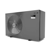
Swimming Pool Heat Pump
Technical Manual
PHNIX reserves the right to discontinue, or change at any time, specifications or designs
without notices and without incurring obligations.

Questions and Answers:

PHNIX PASRW020 Specifications

General IconGeneral
BrandPHNIX
ModelPASRW020
CategoryWater Pump
LanguageEnglish

Summary

Section 1: Summary of Product

Preface

Introduction to the manual and its purpose.

Product Presentation

Overview of the heat pump's capabilities and benefits.

Nomenclature

Explanation of the model designation system.

Principle of Operation

How the heat pump works, including a diagram.

Key Features

Highlights of the unit's durability, efficiency, and eco-friendliness.

Section 2: Performance and Specification

Technical Specifications

Detailed data for various models including capacity, power, and dimensions.

Performance Curves (PASRW015)

Graphs showing COP and QH for PASRW015 model.

Performance Curves (PASRW020)

Graphs showing COP and QH for PASRW020 model.

Performance Curves (PASRW030)

Graphs showing COP and QH for PASRW030 model.

Performance Curves (PASRW035)

Graphs showing COP and QH for PASRW035 model.

Performance Curves (PASRW040)

Graphs showing COP and QH for PASRW040 model.

Performance Curves (PASRW045)

Graphs showing COP and QH for PASRW045 model.

Unit Dimensions

PASRW015 Dimensions

Dimensional drawings for the PASRW015 model.

PASRW020/030/040 Dimensions

Dimensional drawings for PASRW020, 030, and 040 models.

PASRW050S/060S Dimensions

Dimensional drawings for PASRW050S and 060S models.

Component Instructions

Heat Exchanger Details

Description and specifications of the heat exchanger.

Section 3: Installation

Installation Notice and Safety

Critical safety warnings and installation precautions.

Transportation, Inspection, and Handling

Guidelines for safe unit transport, inspection, and handling.

Unpacking and Installation Information

Procedures for unpacking and requirements for installation space.

Hydraulic System Diagram

Schematic of water connections and system layout.

Electrical Wiring

Wiring Diagrams and Connections

Schematics and instructions for electrical hookups.

System Diagrams

Overall system schematic for the heat pump.

Section 4: PC1001 Controller

Controller Interface and Buttons

Explanation of the controller's buttons and their functions.

Controller Display Symbols

Guide to understanding icons and indicators on the controller screen.

Controller Operation Modes

Instructions for unit on/off and selecting operating modes.

Target Temperature Setting

Procedure for adjusting the desired water temperature.

Parameter Setting Overview

Introduction to user and factory parameter types.

Factory Parameter Configuration

Detailed steps for setting factory parameters and passwords.

User Parameter Configuration

Detailed steps for setting user parameters and passwords.

Keyboard Lock and Clock Setting

How to lock/unlock the keypad and set the clock.

Timer Operation Settings

Guide to setting up and managing the unit's timer functions.

Canceling Timer Settings

Procedure to remove configured timer settings.

Download and Upload Operations

Instructions for downloading and uploading unit parameters.

PCB and Troubleshooting

PCB I/O Port Description

Explanation of the connections on the main circuit board.

Troubleshooting Common Issues

List of error codes, reasons, and solutions.

Parameter Reference

Parameter Table

A comprehensive list of all parameters, their codes, and ranges.

Parameter Descriptions

Detailed explanations for defrost, EEV, and fan parameters.

Appendix I: NTC Resistance Table

NTC Thermistor Resistance Chart

Table correlating NTC resistance values with temperatures.

Related product manuals