www.phocos.com 3 | P a g e
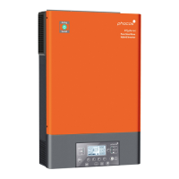
into the Any-Grid display panel’s “RS-232” port:
Any-Grid Cloudlink
For systems with multiple Any-Grids, this connection (marked red) can be made with any of the inverters,
but only a single unit. Remember, all Any-Grids in a synchronised system must be connected to a single
battery bank.
4. Using the provided RJ45 cable with the Cloudlink, plug in the CAN Bus cable into the “CAN” port of the
Hubble battery and the other end into the “CAN” port of the Cloudlink device.
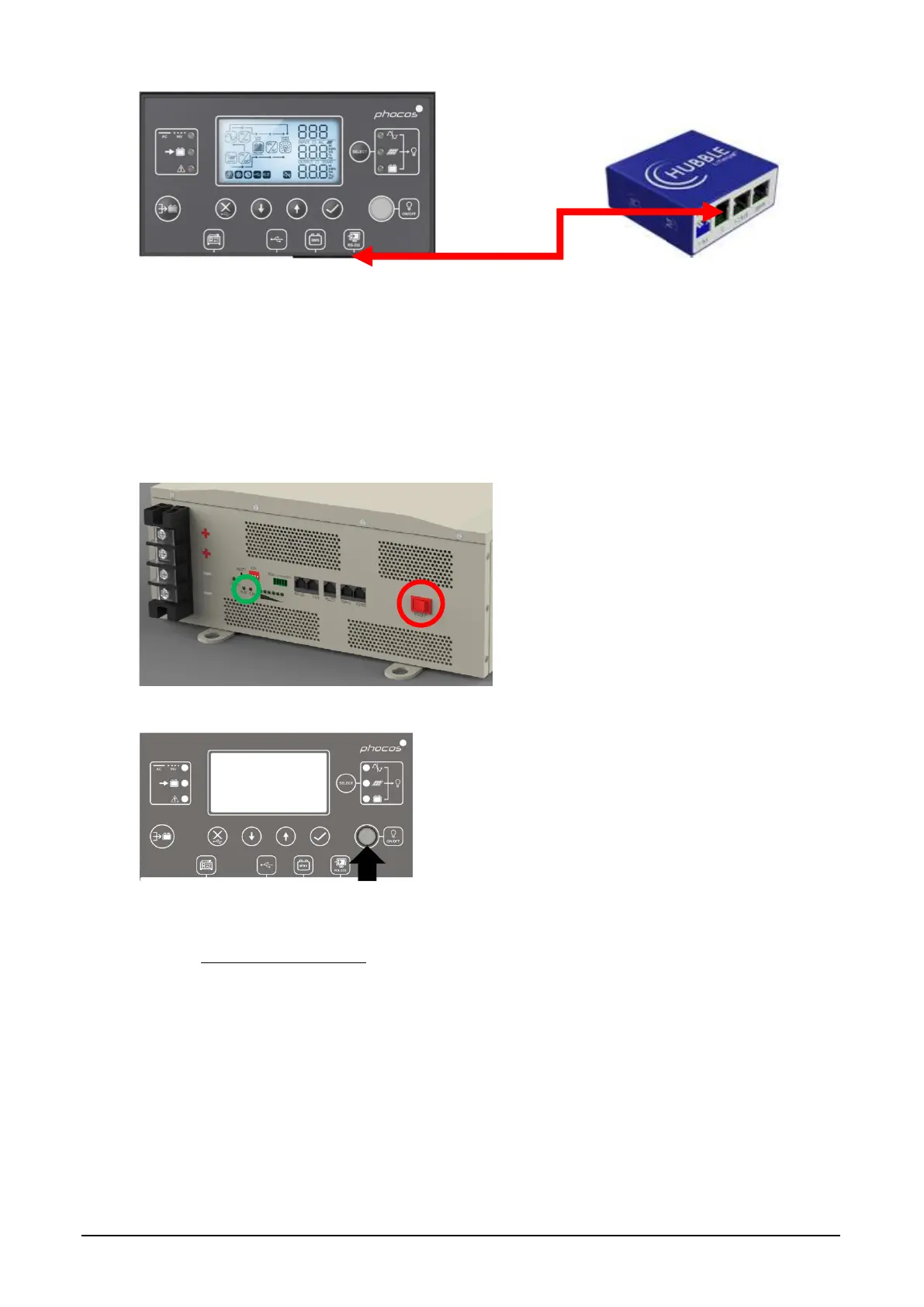
5. Ensure the battery units are wired as outlined in the Hubble battery manual. Turn on each of the battery
units with the power button (circled below in red) and ensure the “RUN” LED blinks is green for all battery
units and that the “ALM” LED is turned off (circled below in green):
6. Turn the “ON/OFF” load power button of the Any-Grid(s) to the ON position (depressed), but make sure no
loads are connected:
The Any-Grid(s) should now be running, the display(s) on.
7. Please refer to the setup guide for the Cloudlink on the Hubble website for setup procedure of the Cloudlink
device at www.hubblelithium.co.za.
8. When the Cloudlink setup is complete, and if no errors are present on the Any-Grid(s) and any of the battery
unit(s), turn on the load breaker, followed by the PV and finally the AC source breaker (if present in the
system).
The commissioning battery unit(s) and Any-Grid(s) is now complete.

 Loading...