Do you have a question about the Phoenix Contact ILC 150 ETH and is the answer not in the manual?
Lists necessary hardware and software for operation.
Overview of the Inline Controller's features and capabilities.
Safety and usage guidelines for explosive environments.
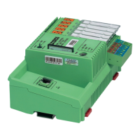
Identifies physical components and connection points on the controller.
Explains indicator lights for local diagnostics.
Describes the function of the mode selector switch.
Provides instructions for installing and uninstalling the controller.
Guidance on power supply selection and 24V main supply data.
Lists required PC WorX/PC WorX Express software versions.
Procedure for assigning IP addresses via BootP server or serial connection.
Accessing and managing parameterization memory via FTP.
System variables to read/write digital I/O states.
Information on controller operating states stored in the diagnostic status register.
Provides additional info about errors indicated in the status register.
Data on I/O points, bus segments, and transmission speed for INTERBUS.
Troubleshooting guide for installation errors.
Instructions for updating the controller's firmware via Ethernet.
| Communication | Ethernet |
|---|---|
| Ethernet Ports | 1 |
| Number of Digital Inputs | 8 |
| Power Supply | 24 V DC |
| Operating Temperature | -25°C to 55°C |
| Programming Software | PC WORX |
| Protection Class | IP20 |
| Memory | 512 kB |
| Communication Protocols | Modbus TCP |