Do you have a question about the Phoenix Contact ILC 151 ETH/XC and is the answer not in the manual?
Describes the manual's scope and target audience.
Outlines critical safety precautions for installation and operation.
Overview of controller features, architecture, and core capabilities.
Safety and installation guidelines for hazardous zone environments.
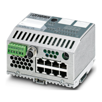
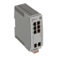
Identifies physical ports, controls, and indicators on the controller.
Explains LED meanings for quick error detection and status monitoring.
Details available network interfaces like Ethernet and serial.
Requirements and connection details for controller power.
Configuration and assignment of I/O terminals.
How to configure network settings via DCP or BootP.
Integration and configuration within a PROFINET network.
Using SD card for main or additional data storage.
Overview of controller error states and operational flags.
Detailed error information including location and code.
Detailed specifications including dimensions, electrical characteristics, and environmental ratings.
Troubleshooting guide for common installation and operational errors.
Procedure for upgrading the controller's internal software.
| Communication Interface | Ethernet |
|---|---|
| Number of Digital Outputs | 4 |
| Port Type | RJ45 |
| Power Supply Voltage | 24 V DC |
| Degree of Protection | IP20 |
| Protocols | PROFINET, Modbus TCP |
| Operating Temperature Range | -25°C to 60°C |