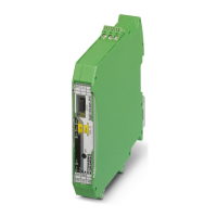
RAD-...-IFS
154 / 198
PHOENIX CONTACT 105542_en_05
LED bar
graph, only
yellow LED
is on
Connection with low receive
signal
• Check whether the antennas are connected and aligned properly.
• Make sure that the antenna connections are tight and free from cor-
rosion.
• Install the antenna at a higher point. Adhere to the Fresnel zone.
• Use a different antenna with higher antenna gain or use shorter
cables with lower signal attenuation.
• Check whether there is another transmitting antenna in close prox-
imity. Position the antenna further away from all other antennas (at
least 1 m in the horizontal direction or 0.6 m in the vertical direction).
• Make sure that the power supply is sufficiently high.
• Make sure that there is no connection between the core and the
shield of the cable in the connected antenna system.
Several repeaters/slaves at the
master wireless module
• No action required, normal display for a wireless network with more
than one repeater/slave. The signal strength is displayed on the
repeaters/slaves. The signal strength always relates to the directly
connected, overlapping wireless module.
In I/O data mode
ERR flash-
ing slowly
(1.4 Hz)
Double assignment of the
I/O MAP address, two input
modules have the same
I/O MAP address in a network.
• The I/O MAP address of an input module may only appear once in
the network. Use the white thumbwheel to set different I/O MAP
addresses.
Missing input module
Example: an output module is
not assigned the corresponding
input module with the same
I/O MAP address.
• Check whether an input module with the same I/O MAP address has
been assigned to every output module.
• Use the white thumbwheel on the extension module to set the
I/O MAP address (01 ... 99). The input module must be provided with
the same I/O MAP address as the assigned output module at anoth-
er station.
Missing output module
Example: an input module is not
assigned the corresponding
output module with the same
I/O MAP address.
• Check whether an output module with the same I/O MAP address
has been assigned to every input module.
• Use the white thumbwheel on the extension module to set the
I/O MAP address (01 ... 99). The output module must be provided
with the same I/O MAP address as the assigned input module at
another station.
RAD ID changed
Example: the yellow thumb-
wheel setting has accidentally
been modified and the modifica-
tion has not yet been confirmed
via the SET button.
• Check the RAD ID setting on the yellow thumbwheel of the wireless
module.
• If necessary, set the correct RAD ID and press the SET button.
Table 9-1 Detecting and removing errors: wireless module
LED,
wireless
module
Current state and possible
cause
Solution

 Loading...