RAD-...-IFS
54 / 198
PHOENIX CONTACT 105542_en_05
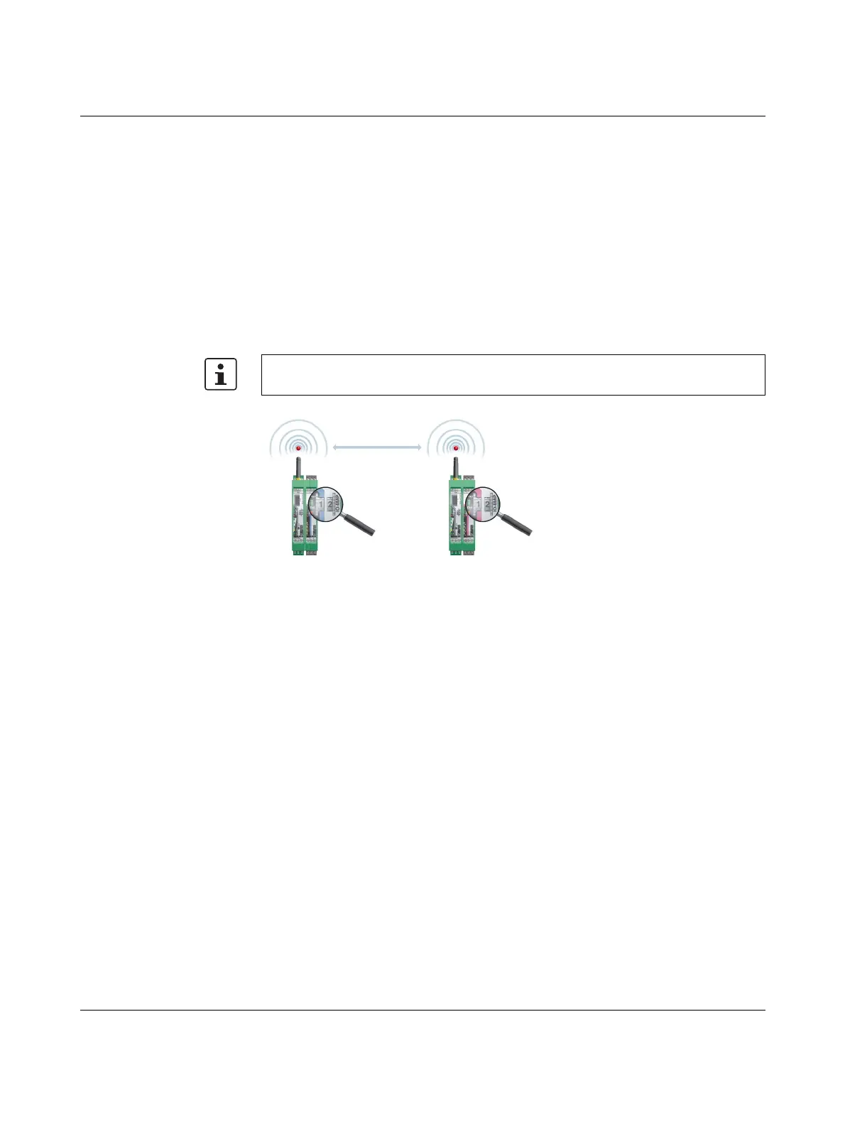
Wireless module in I/O data mode
– The input module must be provided with the same I/O MAP address as the assigned
output module at another station (I/O mapping). Output modules with the same
I/O MAP address may appear several times at different stations in the network.
– The I/O MAP address of an input module may only appear once in the network.
– The channels of the input module are directly assigned to the channels of the output
module:
Figure 4-23 Input module and output module with the same address
Wireless module in PLC / Modbus/RTU mode
–Output modules must not have the same I/O MAP address as input modules. Excep-
tion: output modules with the same I/O MAP address may appear several times at dif-
ferent stations in the network.
– The I/O MAP address of an input module may only appear once in the network.
– The input and output data is saved in a Modbus memory map in the master wireless
module. You can read or write the process data via the serial interface of the master
wireless module (RAD ID = 01) using the Modbus/RTU command. The process data
tables can be found starting at page 68.
4.10 Startup time of the wireless station
Once a wireless station has been started up (power “ON”), it will take the wireless module
several seconds until it is ready for operation. Every connected I/O extension module in-
creases the startup time. Accordingly, a complete wireless station with 32 I/O extension
modules may take several minutes to start up. Only after this time has elapsed is the wire-
less station ready for operation.
Input module Output module
Channel 1 Channel 1
Channel 2 Channel 2
... ...
It is not possible to individually assign the channels of the input and output modules.

 Loading...

