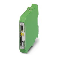
RAD-...-IFS
156 / 198
PHOENIX CONTACT 105542_en_05
Table 9-2 Detecting and removing errors: I/O extension module
LED,
I/O module
Current state and possible
cause
Solution
PWR off
No power supply, mains proba-
bly switched off
• Switch on the mains, restore the power supply.
DAT off
No communication between
wireless module and
I/O extension module. The wire-
less module is probably in “serial
data” mode.
• Check whether the I/O extension module is properly snapped onto
the DIN rail connector and whether it is connected to the wireless
module.
• Check the operating mode of the wireless module using the
PSI-CONF software. The wireless module must be in “I/O data”,
“PLC / Modbus/RTU” mode or in dual mode (see page 38).
• Reset the wireless module to the default settings (I/O data mode,
see page 30), if necessary.
ERR on
Critical internal error
Example: technical defect
• Please contact Phoenix Contact technical support.
ERR flash-
ing slowly
(1.4 Hz)
I/O MAP address changed
Example: the white thumbwheel
setting has accidentally been
modified and the modification
has not yet been confirmed via
the SET button.
• Check the I/O MAP address setting on the white thumbwheel of the
I/O extension module.
• If necessary, set the correct I/O MAP address and press the SET
button on the wireless module.
In I/O data mode
ERR flash-
ing fast
(2.8 Hz)
Missing input module
Example: an output module is
not assigned the corresponding
input module with the same
I/O MAP address.
• Check whether an input module with the same I/O MAP address has
been assigned to every output module.
• Use the white thumbwheel on the extension module to set the
I/O MAP address (01 ... 99). The input module must be provided with
the same I/O MAP address as the assigned output module at anoth-
er station.
No bus communication,
no wireless connection present
• See measures for the wireless module, page 153
In PLC / Modbus/RTU mode
ERR flash-
ing fast
(2.8 Hz)
No Modbus communication
(safe state of outputs, depend-
ing on DIP switch settings)
• Check the communication line between the Modbus/RTU controller
and the master wireless module using RAD ID 01.
• Check the wiring of the RS-232/RS-485 connections on the master
and the PLC.
• Check the serial interface settings (baud rate, parity, data bits, and
stop bits) on the master and the PLC (from page 38 onwards).
• Check whether the I/O extension module is properly snapped onto
the DIN rail connector.
• Use the PSI-CONF software to check if the wireless module is in
“PLC / Modbus/RTU” mode or in dual mode (see page 38).
• Press the SET button on the wireless module or carry out a power up
in order to read the station structure.
No bus communication,
no wireless connection present
• See measures for the wireless module, page 153

 Loading...