Configuration and startup
105542_en_05 PHOENIX CONTACT 45 / 198
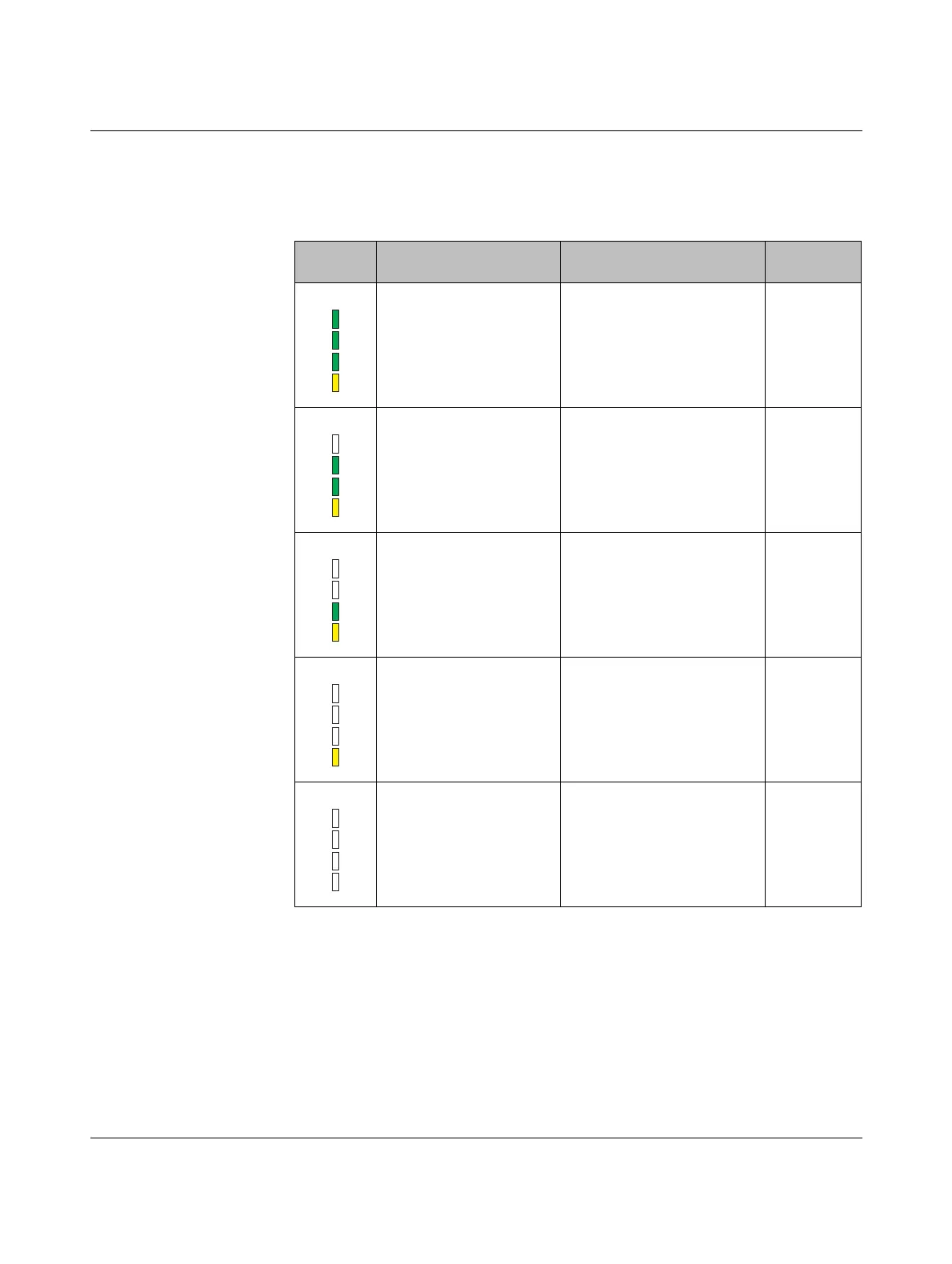
4.7.1 LED bar graph
The LED bar graph indicates the receive signal strength.
Table 4-6 LED bar graph
Bar graph LEDs Receive signal RSSI
voltage
All LEDs light up Connection with maximum
receive signal
2.5 V ... 3 V
One yellow and two green
LEDs light up
Connection with very good
receive signal
2 V ... 2.5 V
One yellow and one green
LED light up
Connection with good receive
signal
1.5 V ... 2 V
One yellow LED lights up Connection with weak receive
signal
1 V ... 1.5 V
Off Not connected, configuration
mode or overload
1
1
By default upon delivery, the receive preamplifier is activated. The transmission power is set so that the
devices can cover the greatest possible distances. Therefore, if the devices are operated directly next to
one another the receiver may become overloaded. In this case, remove the antennas, increase the dis-
tance between the devices and antennas or reduce transmission power using the PSI-CONF software
(from page 38 onwards).
0V

 Loading...

