PLC / Modbus/RTU
105542_en_05 PHOENIX CONTACT 63 / 198
• Activate dual mode as shown in the following example: “Configuration via PSI-CONF
software” on page 60.
• Set the Modbus ID of each wireless module using the yellow thumbwheel.
• You can connect a maximum of 32 I/O extension modules to a wireless station. Use the
white thumbwheel on the I/O extension module to set the I/O MAP address. For infor-
mation on addressing extension modules, please refer to page 53 onwards.
• A wireless network can have a maximum of 99 I/O extension modules.
6.2.1 Configuration via PSI-CONF software
• Start the PSI-CONF software (see page 38).
• Create a new network project.
• Follow the software wizard.
In order to enable the master wireless module to communicate with a controller via the
RS-232 or RS-485 interface, you must set the interface parameters. Please note that the
controller settings must match the settings of the wireless module.
You can monitor the Modbus connection between the controller and the wireless module via
a watchdog.
The function codes, error codes and registers are the same as those in
PLC / Modbus/RTU mode. For addition information, please refer to page 66 onwards.
– The Modbus address is a unique address in the Modbus network. In dual mode, the
Modbus address is the RAD ID.
– In case Modbus slave address “01” has already been assigned to another Modbus
device: The address of the master wireless module can only be changed via the
PSI-CONF software. You can assign an address between 1 ... 247.
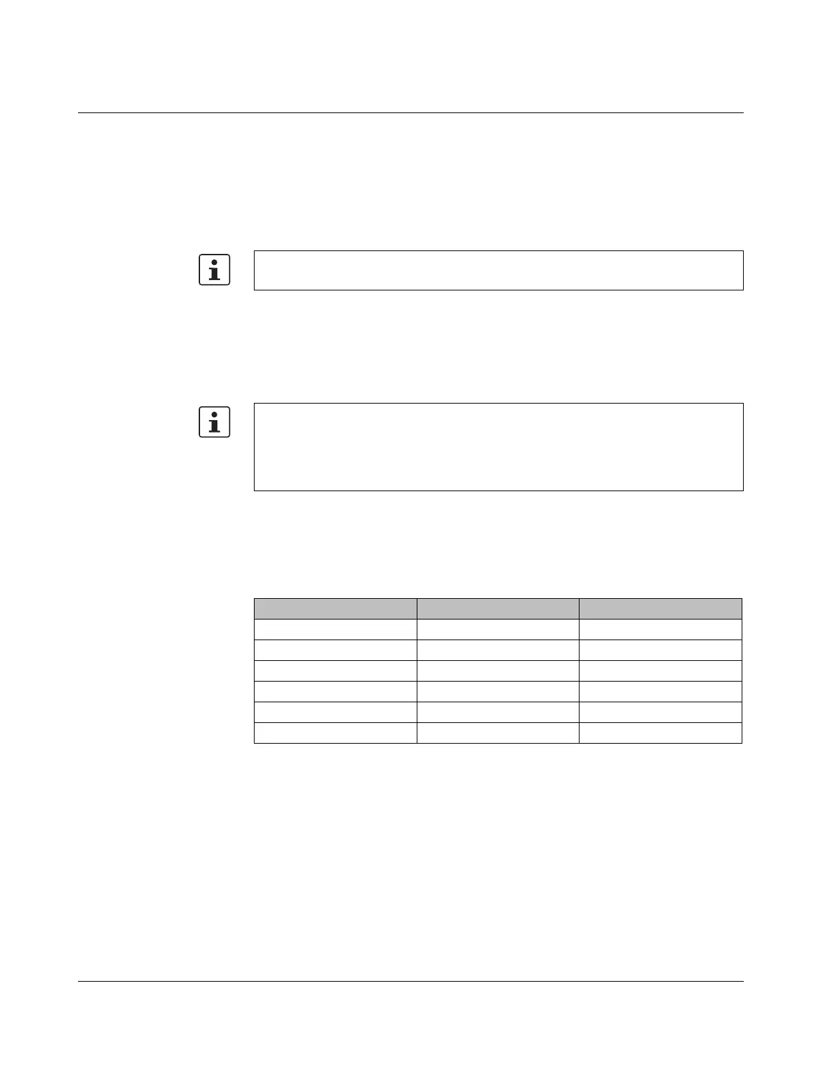
Table 6-2 Configuration via PSI-CONF software
Parameter Possible values Default setting
Interface type RS-232, RS-485 RS-232
Data rate 300 bps ... 115200 bps 19200 bps
Parity None, even, odd None
Number of stop bits 1; 2 1
Number of data bits 8 8
Modbus address 1 ... 247 1

 Loading...

