RAD-....-IFS
82 / 198
PHOENIX CONTACT 105542_en_05
6.6.10 RSSI signal and error code registers
The RSSI values indicate the received signal strength on the wireless module. You can read
the RSSI values via the serial interface of the master wireless module (RAD ID = 01) using
Modbus/RTU commands. The RSSI values of all wireless modules in the network are within
address range 35001 ... 35250.
Bit 08 = error on IFS bus
If an error is present on the IFS bus, the register value is 1 (e.g., local bus error, because the
input or output module is disconnected from the DIN rail connector). If no error is present on
the IFS bus, the register value is 0.
– Bits 9 ... 15 are reserved.
–Values <255 indicate the RSSI value in -dBm.
– Value 255 means that the RSSI value is invalid or the device cannot be reached.
Example for reading the RSSI register of the station with RAD ID = 2:
Function code 04, start address 5001 (hex1389)
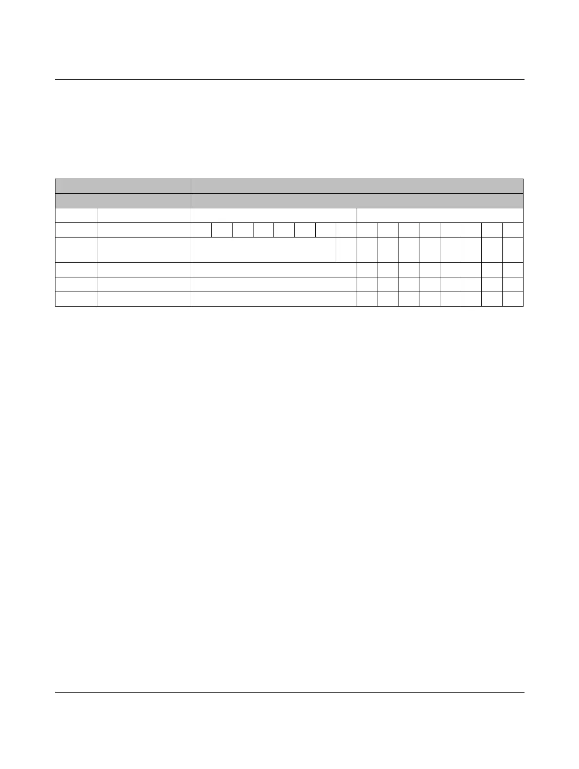
Table 6-17 RSSI signal and error code registers
Address range 35001 ... 35250
Modbus function code fc 04
Address Wireless module High byte Low byte, RSSI value
15 14 13 12 11 10 09 08 07 06 05 04 03 02 01 00
35001 RSSI - RAD ID = 1
(master)
Reserved
IFS
XXXXXXXX
35002 RSSI - RAD ID = 2 Reserved XXXXXXXX
... ... Reserved XXXXXXXX
35250 RSSI - RAD ID = 250Reserved XXXXXXXX

 Loading...

